
Methods and Apparatus for Simulation Of Fluid Motion Using Procedural Shape Growth

a technology of fluid motion and shape growth, applied in the field of methods and apparatus for simulation of fluid motion using procedural shape growth, can solve the problems of increasing processing complexity, still involving considerable computation, and thus time, and achieve the effect of less processing power and faster rendering of frames

Active Publication Date: 2013-05-23
ADOBE INC
View PDF6 Cites 21 Cited by
  • Summary
  • Abstract
  • Description
  • Claims
  • Application Information

AI Technical Summary

Benefits of technology

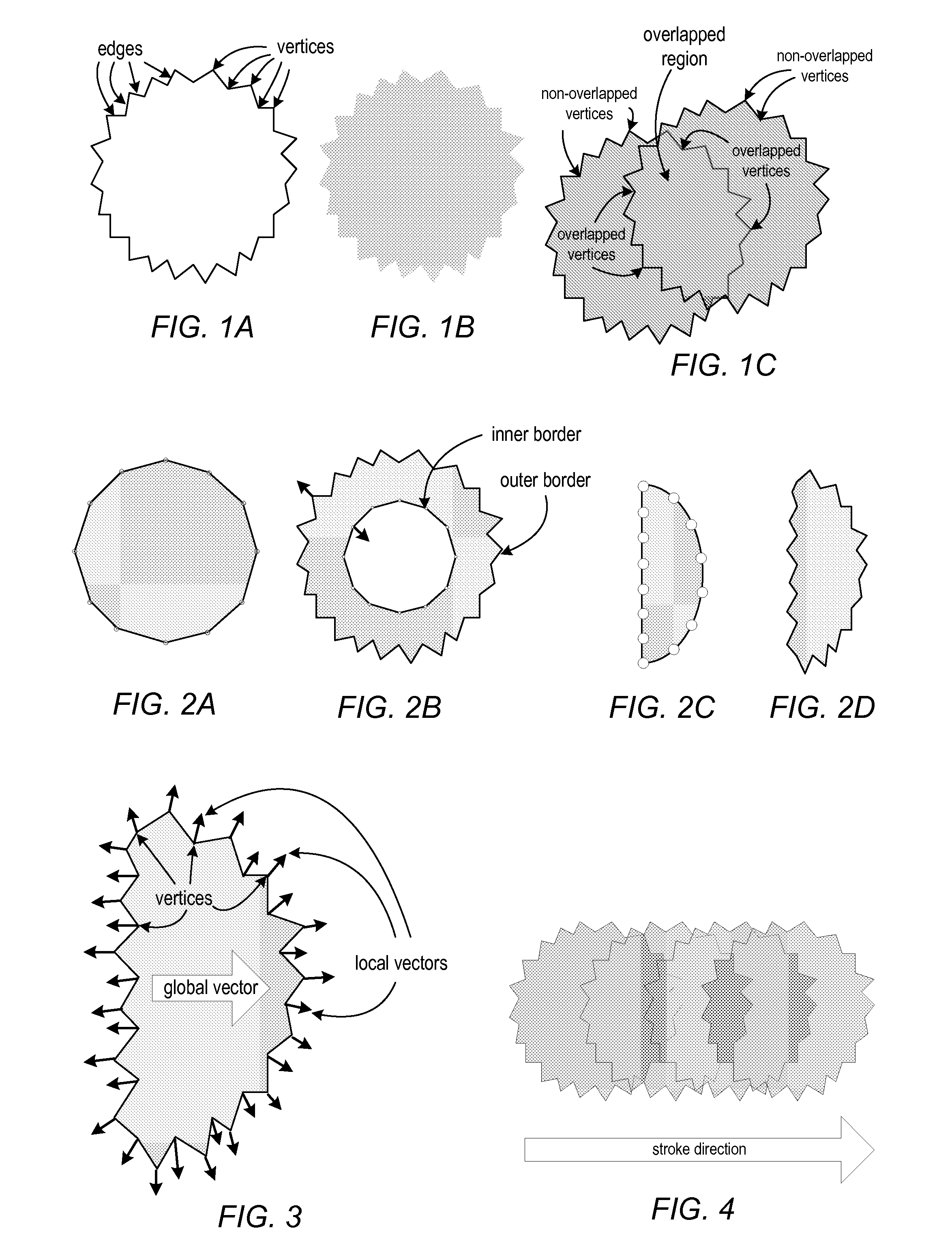
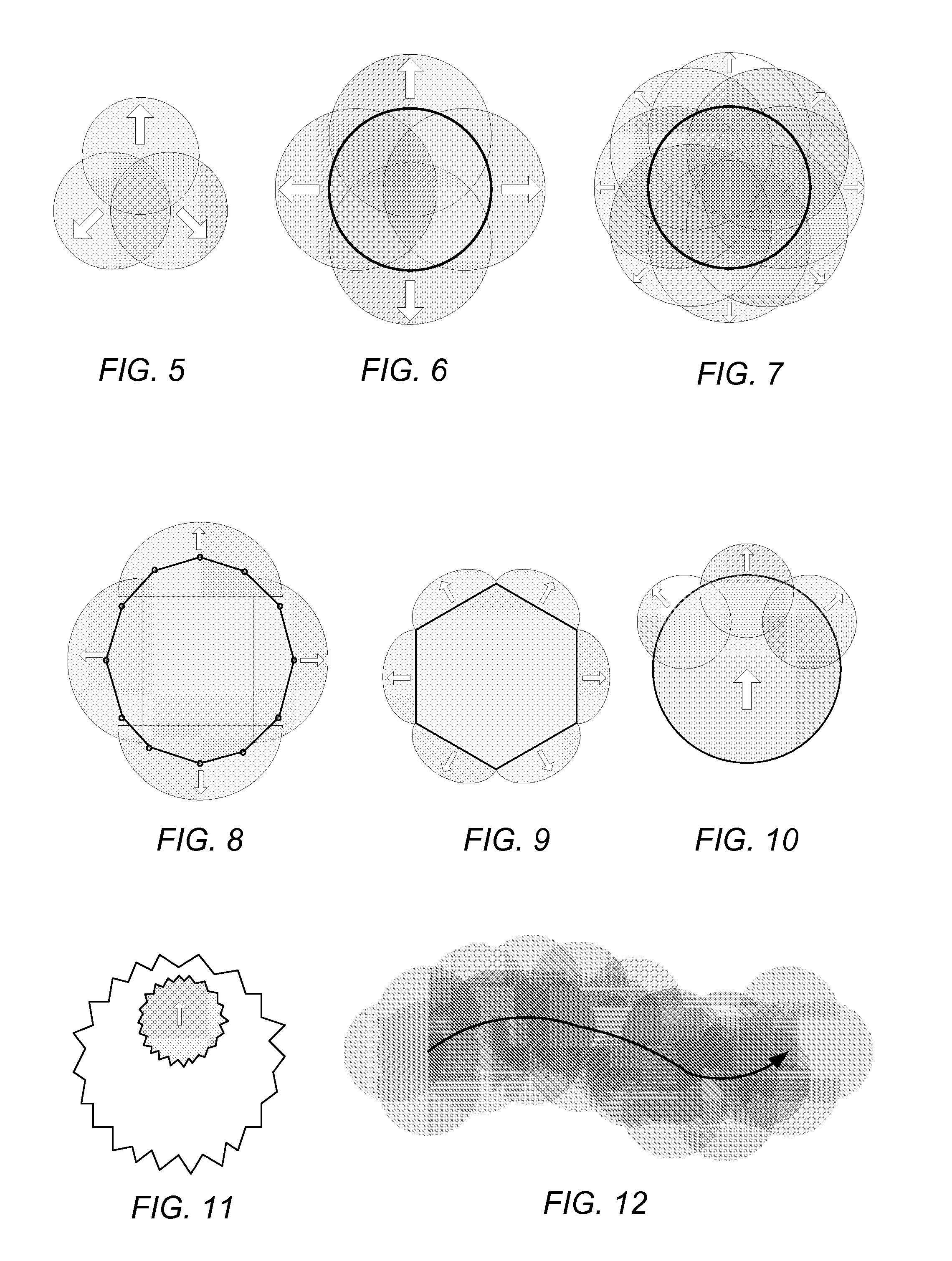
The patent describes a method and apparatus for simulating fluid motion using a vector-based approach. This technique involves depositing polygons on a digital canvas and growing them by moving the vertices of the polygons. The polygons may overlap and have smooth edges when zoomed in. The technique requires less processing power than conventional raster-based methods and can render frames faster. It can be used in applications such as simulated painting, where fluid motion effects are important. The technique also allows for blending with other polygons and can account for wetness in overlapping polygons.

Problems solved by technology

Even if the fluid motion effect being simulated is relatively simple and thus the computation at each pixel is relatively straightforward, this still involves considerable computation, and thus time, due to the large number of pixels being individually processed.
If more complicated fluid motion effects are being simulated, the computations at each pixel become more complicated, and thus the processing may take much longer.
In addition, raster-based techniques tend to exhibit pixilation when zoomed in.

Method used


Image

  • Methods and Apparatus for Simulation Of Fluid Motion Using Procedural Shape Growth
  • Methods and Apparatus for Simulation Of Fluid Motion Using Procedural Shape Growth
  • Methods and Apparatus for Simulation Of Fluid Motion Using Procedural Shape Growth

Examples


example implementations

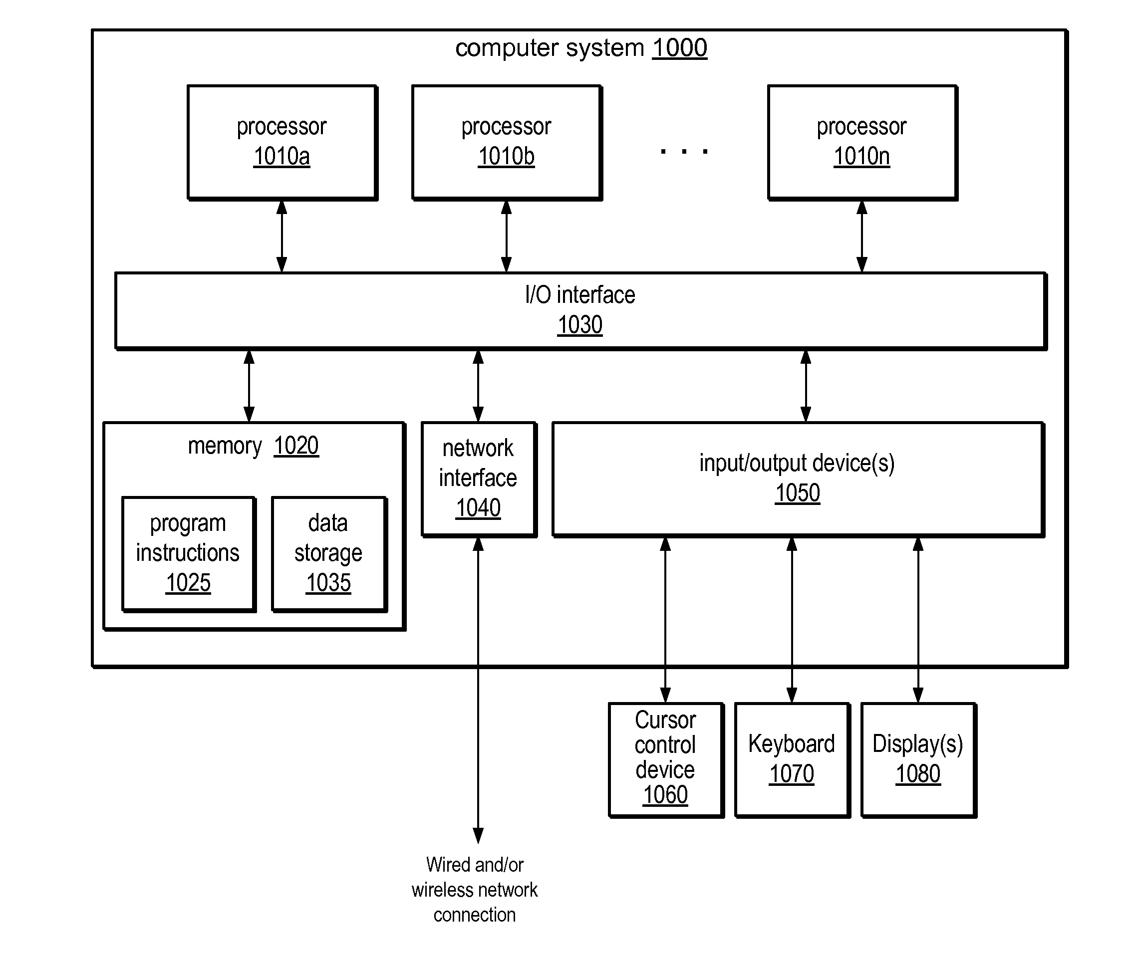
[0109]FIG. 27 illustrates a fluid motion simulation module that may implement embodiments of the vector-based, fluid motion simulation techniques illustrated in FIGS. 1 through 26. Module 920 may include an applicator submodule 926 that provides a painting technique and that employs a user interface 924 similar to the example user interface illustrated in FIGS. 21 and 22A-22C to deposit polygons to a canvas 910. Module 920 may also include a growth and blending submodule 928 that implements a fluid motion simulation technique that grows and blends deposited polygons as illustrated in FIGS. 24 through 26. FIG. 28 illustrates an example computer system on which embodiments of module 920 may be implemented. Module 920 may receive as input a digital canvas 910. While FIG. 27 shows the digital canvas 910 as blank, the canvas 910 may be a digital image or photograph, and may be an image that was previously created with module 920. Applicator submodule 926 may receive user input 912, for e...


PUM


Abstract

Methods and apparatus for simulating fluid motion using procedural shape growth. In a vector-based, fluid motion simulation technique, fluid location may be defined by groups of one or more polygons deposited on a digital canvas. Two or more polygons may overlap. The polygons may be semitransparent. To simulate fluid motion, vertices that specify the edges of each deposited polygon are independently moved. By moving the vertices, a polygon may grow, and fluid motion effects may be simulated, including but not limited to directional flow and blending effects. A randomization technique may be applied to the movement at each vertex to simulate the non-uniform spreading of fluids. Overlapped polygons may be blended with overlapping polygons to simulate the mixing of fluids. The technique may be applied, for example, in watercolor painting simulation, where groups of one or more polygons are deposited using brush strokes.

Description

BACKGROUNDDescription of the Related Art[0001]Conventionally, the simulation of fluid motion in computer graphics has been handled using raster-based techniques. That is, fluids and gasses have been simulated on a grid of cells or pixels, and fluid motion is computed between pixels on the grid. These conventional techniques involve processing each pixel on the grid, where neighboring pixels are examined and one or more fluid dynamics equations are computed at the pixel. In high-resolution applications in particular, such as high-resolution painting applications, a large number of pixels may have to be processed at each of multiple iterations. Even if the fluid motion effect being simulated is relatively simple and thus the computation at each pixel is relatively straightforward, this still involves considerable computation, and thus time, due to the large number of pixels being individually processed. If more complicated fluid motion effects are being simulated, the computations at ...

Claims


Application Information

Patent Timeline
IPC IPC(8): G06G7/50
CPCG06T13/80G06T11/001G06T2210/24
Inventor MECH, RADOMIRITO, DAICHI
Owner ADOBE INC
Learn More