Method of manufacturing a molded sensor subassembly

a manufacturing method and sensor technology, applied in the direction of structural/machine measurement, instruments, non-metallic protective coating applications, etc., can solve the problems of disadvantageous extremely complex production methods, complex production process, and inability to meet the needs of sensor production, etc., to achieve the effect of negative affecting the sensor

Inactive Publication Date: 2013-05-30
ZF FRIEDRICHSHAFEN AG
View PDF5 Cites 5 Cited by
  • Summary
  • Abstract
  • Description
  • Claims
  • Application Information

AI Technical Summary

Benefits of technology

The present invention proposes a simple method for producing an insert molded sensor assembly. This method allows for the insert molding of a circuit board with sensor technology accommodated on it and ensures that the insert molding material does not negatively affect the sensor. The method achieves this by supporting the circuit board with pins that have a defined distance to the tool contact surface and thus allow for a controlled thickness of the insert molding material over the sensor technology. This method is particularly cost-effective for producing sensor assemblies, such as rotational speed sensors for vehicles.

Problems solved by technology

These production methods are however disadvantageously extremely complex.
This production process, which for producing the insert molded circuit board provides for a pre-mold and then the final insert molding, is also very complex.
In the course of insert molding such a circuit board in a tool, this can result in the thickness of the molding material above the sensor element fluctuating by the tolerance of the circuit board.
As a result, the formed sensor assembly, particularly the sensor element, can be impaired in the function thereof.

Method used


Image

  • Method of manufacturing a molded sensor subassembly
  • Method of manufacturing a molded sensor subassembly
  • Method of manufacturing a molded sensor subassembly

Examples


Embodiment Construction

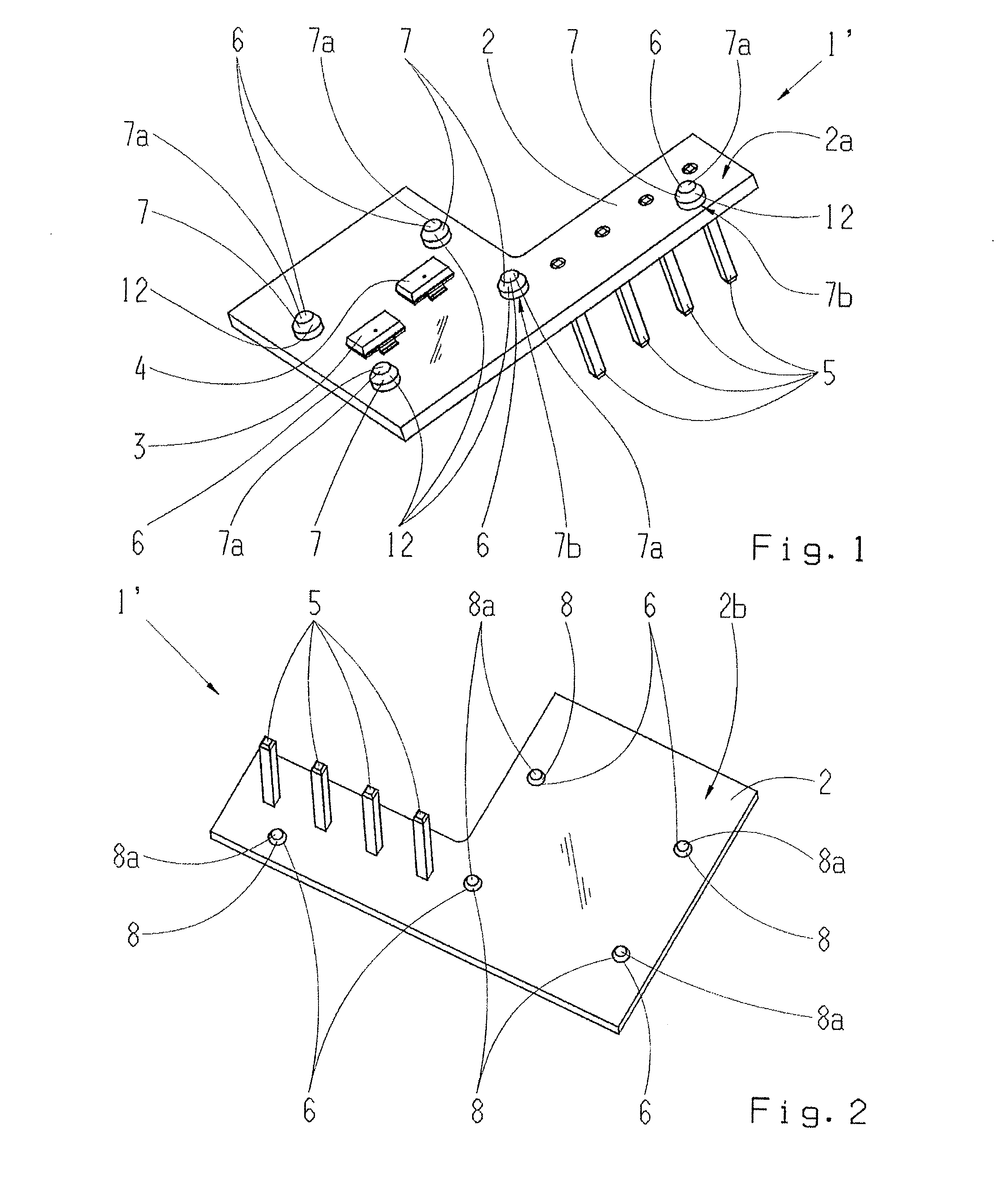
[0033]FIG. 1 shows schematically from above, as an example, a semi-finished sensor assembly 1′, which is obtained in the course of the first step 110 of the method in the scope of the proposed method 100 shown in FIG. 8.

[0034]The semi-finished sensor assembly 1′ has a circuit board 2 which is formed as an FR4 circuit board. A first 3 and a second 4 sensor element are received, or disposed, particularly soldered, on a first planar side 2a of the circuit board 2. The sensor elements 3, 4 are each formed as ICs, presently as Hall ICs, wherein a sensing means is disposed within the respective IC.

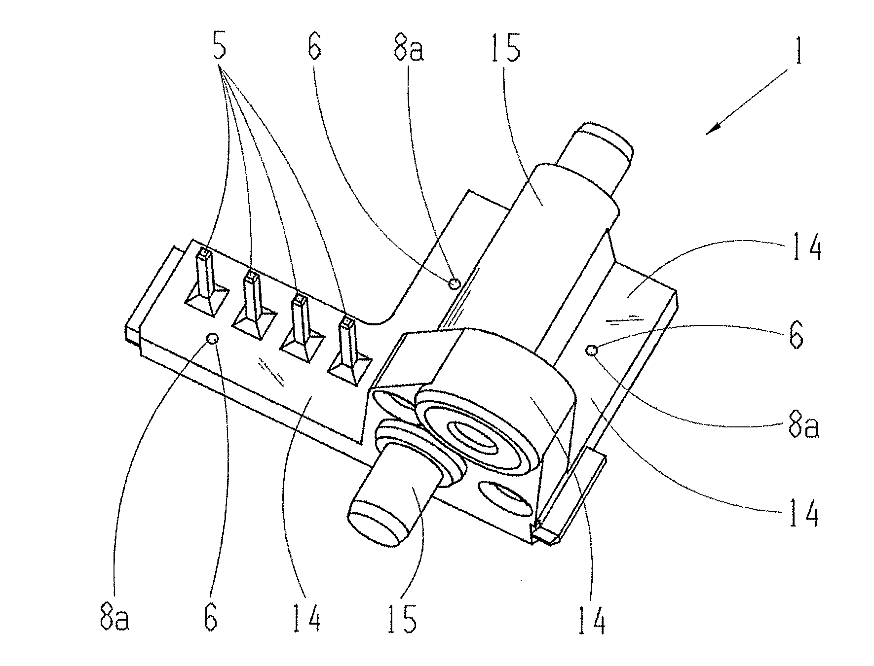
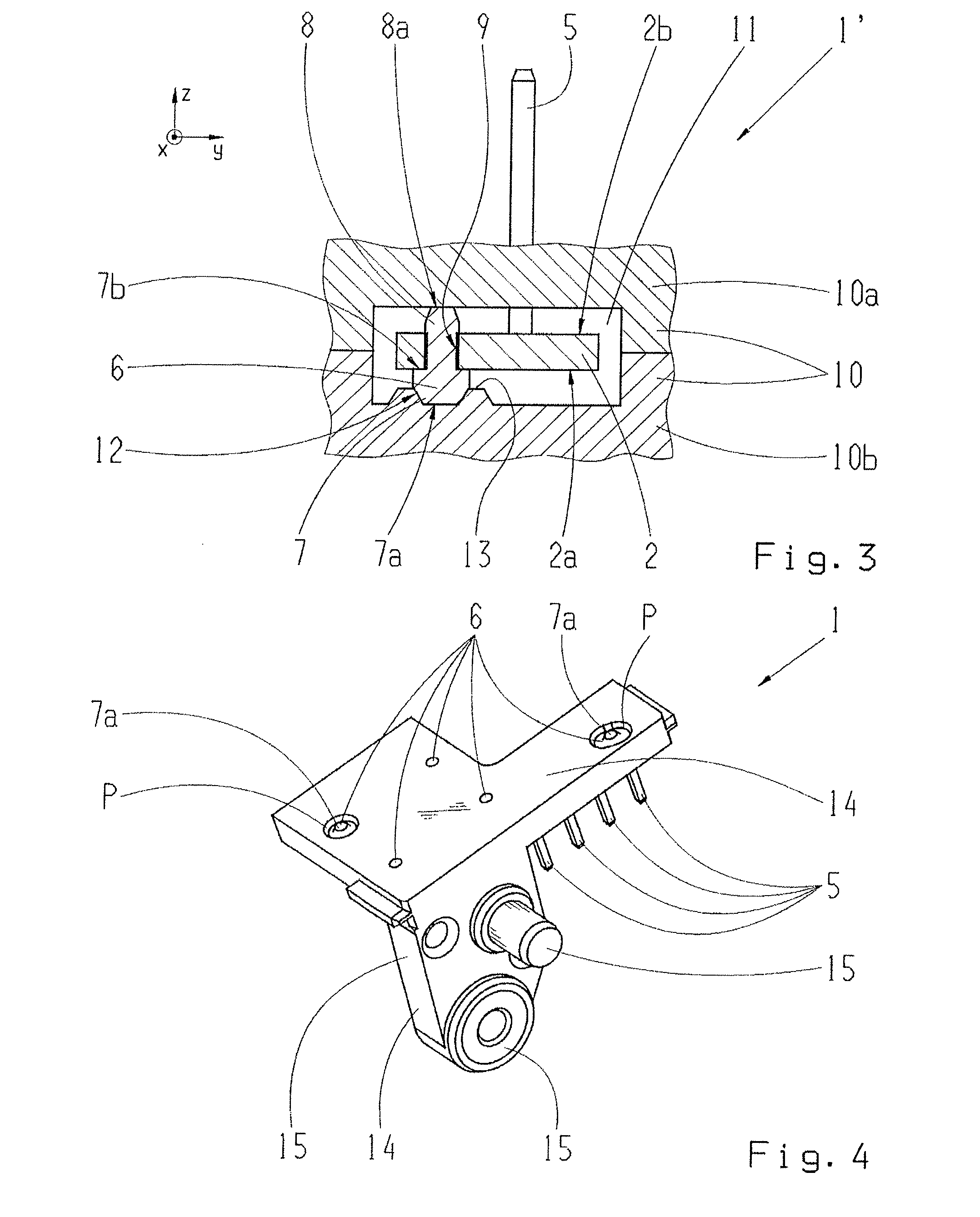
[0035]Furthermore, plug contacts 5 are formed on the circuit board 2 for the purposes of connection, extending away from the underside or second planar side 2b of the circuit board, that is, transversely to the extension plane of the circuit board 2, see also FIG. 2.

[0036]For producing an insert molded sensor assembly 1, the circuit board 2 has a plurality of pins 6, particularly metal pins 6, w...


PUM


Abstract

A method of producing an insert molded sensor assembly having at least one sensor element accommodated on a first side of a circuit board of the sensor assembly. During a first step, a plurality of pins are introduced and penetrate through the circuit board. The circuit board, including the at least one sensor element, is then disposed, during a second step, into a two-part insert mold tool so that the pins are supported on both sides of the circuit board in a direction transverse to a plane defined by the circuit board. A defined spacing distance, between a surface of the sensor element and the insert mold tool, is produced by the pins. During a third step of the method, the insert mold tool is filled with insert molding material, particularly a duroplast.

Description

[0001]This application claims priority from German patent application serial no. 10 2011 087 328.7 filed Nov. 29, 2011.FIELD OF THE INVENTION[0002]The present invention relates to a method of manufacturing a molded sensor subassembly.BACKGROUND OF THE INVENTION[0003]In the prior art, it is known for producing a sensor, particularly a robust sensor suitable for motor vehicle applications, particularly transmission applications, to first form a pre-mold, on which the sensing element or sensor element is accommodated, and after this, to encase, or insert mold the arrangement of the pre-mold and the sensor element together. One such procedure is shown for example in the document DE 10 2009 000 428 A1. In addition, the document DE 10 2008 064 047 A1 discloses a similar method for producing a sensor, wherein the sensor element is first insert molded, then is mechanically connected to a carrier element, and next is insert molded again together with the carrier element. These production met...

Claims


Application Information

Patent Timeline
IPC IPC(8): H05K3/28G01M13/02
CPCH05K3/284G01M13/02Y10T29/49002H05K2201/10303H05K2203/1316H05K2201/10151
Inventor WALLNER, HERBERTFRIEDL, ROLAND
Owner ZF FRIEDRICHSHAFEN AG
Why Eureka
Try Eureka