Patient interface device including a dynamic self adjustment mechanism

a patient interface and dynamic technology, applied in the direction of breathing masks, respirators, breathing protection, etc., can solve the problems of mask dislodge, seal breakage, patient interface devices are typically worn,

Active Publication Date: 2013-05-30
KONINKLIJKE PHILIPS ELECTRONICS NV
View PDF8 Cites 97 Cited by
  • Summary
  • Abstract
  • Description
  • Claims
  • Application Information

AI Technical Summary

Benefits of technology

[0012]These and other objects, features, and characteristics of the present invention, as well as the methods of operation and functions of the related elements of structure and the combination of parts and economies of manufacture, will become more apparent upon consideration of the following description and the appended claims with reference to the accompanying drawings, all of which form a part of this specification, wherein like reference numerals designate corresponding parts in the various figures. It is to be expressly understood, however, that the drawings are for the purpose of illustration and description only and are not intended as a definition of the limits of the invention.

Problems solved by technology

For such patient interface devices, a key engineering challenge is to balance patient comfort against mask stability, i.e., the patient interface device stays properly fitted on the user.
This is particularly true in the case of treatment of OSA, where such patient interface devices are typically worn for an extended period of time.
As a patient changes sleeping positions through the course of the night, masks tend to become dislodged, and the seal can be broken.
A dislodged mask can be stabilized by increasing strapping force, but increased strapping force tends to reduce patient comfort.
This design conflict is further complicated by the widely varying facial geometries that a given mask design needs to accommodate.
This creates difficulty in providing a single patient interface design that fits a range of users.
If this pressure is not able to be managed effectively, either or both of a poor fit or patient discomfort will result, thereby limiting the effectiveness of the device.

Method used


Image

  • Patient interface device including a dynamic self adjustment mechanism
  • Patient interface device including a dynamic self adjustment mechanism
  • Patient interface device including a dynamic self adjustment mechanism

Examples


Embodiment Construction

[0021]As used herein, the singular form of “a”, “an”, and “the” include plural references unless the context clearly dictates otherwise. As used herein, the statement that two or more parts or components are “coupled” shall mean that the parts are joined or operate together either directly or indirectly, i.e., through one or more intermediate parts or components, so long as a link occurs. As used herein, “directly coupled” means that two elements are directly in contact with each other. As used herein, “fixedly coupled” or “fixed” means that two components are coupled so as to move as one while maintaining a constant orientation relative to each other.

[0022]As used herein, the word “unitary” means a component is created as a single piece or unit. That is, a component that includes pieces that are created separately and then coupled together as a unit is not a “unitary” component or body. As employed herein, the statement that two or more parts or components “engage” one another shal...


PUM


Abstract

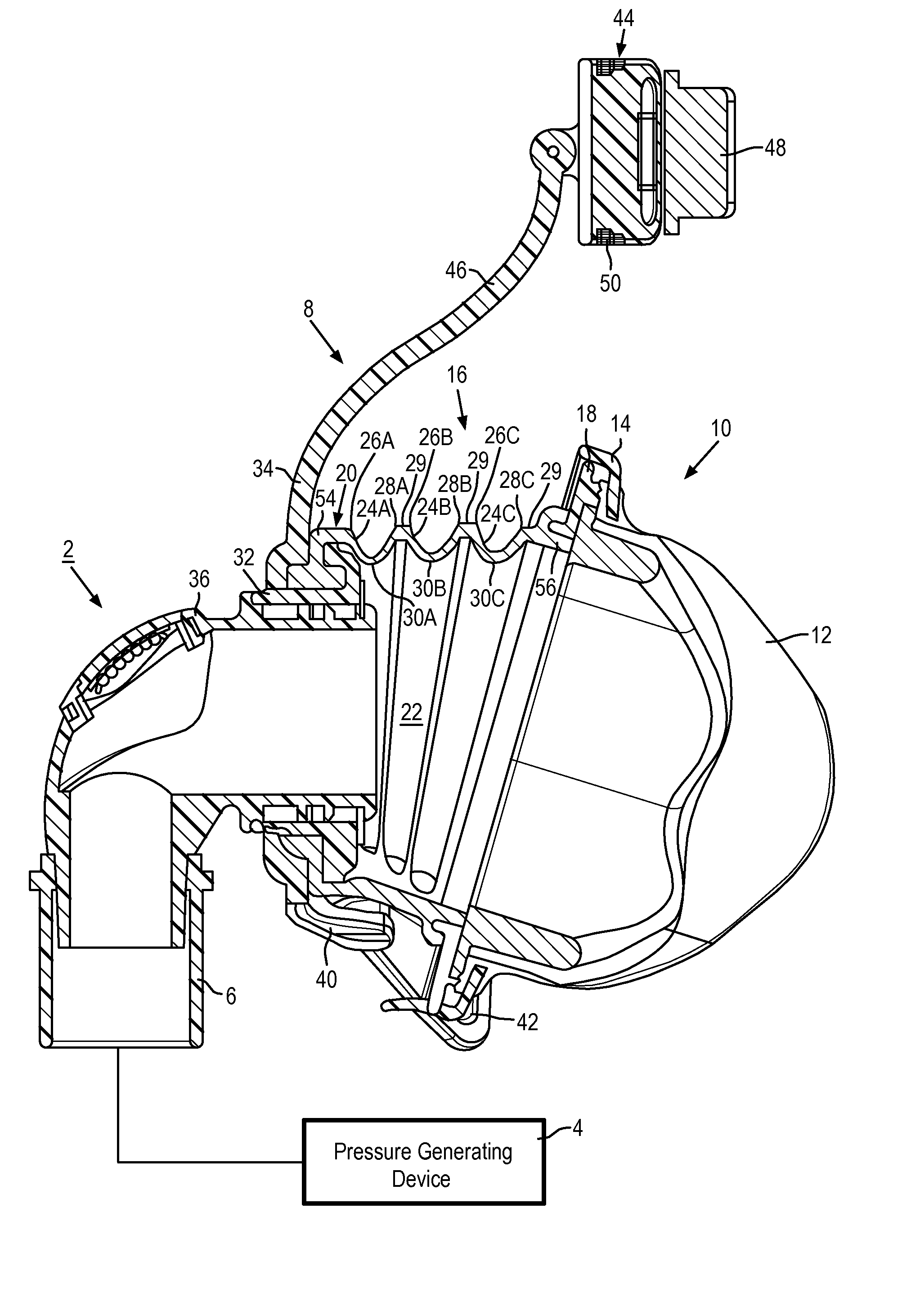
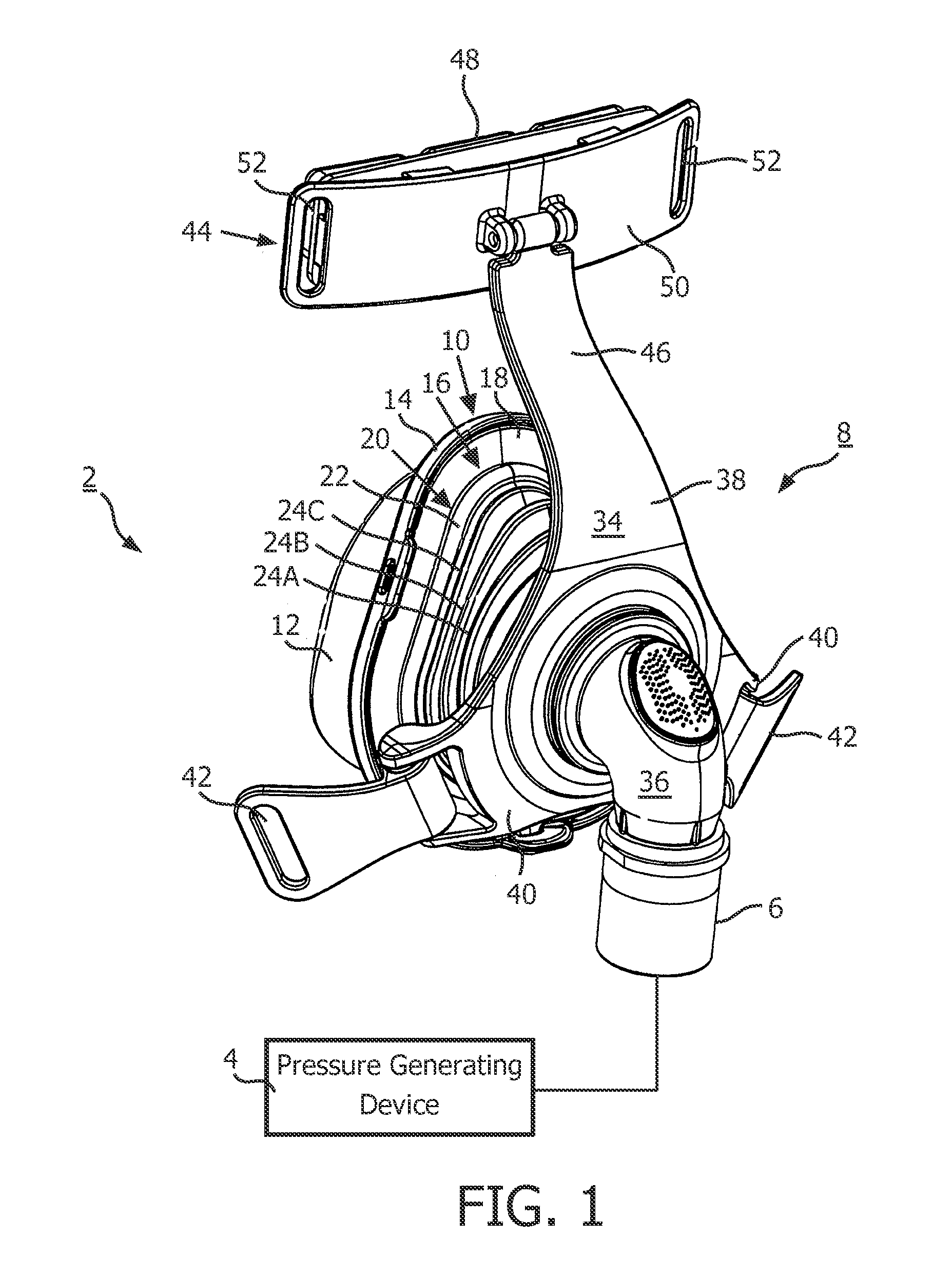
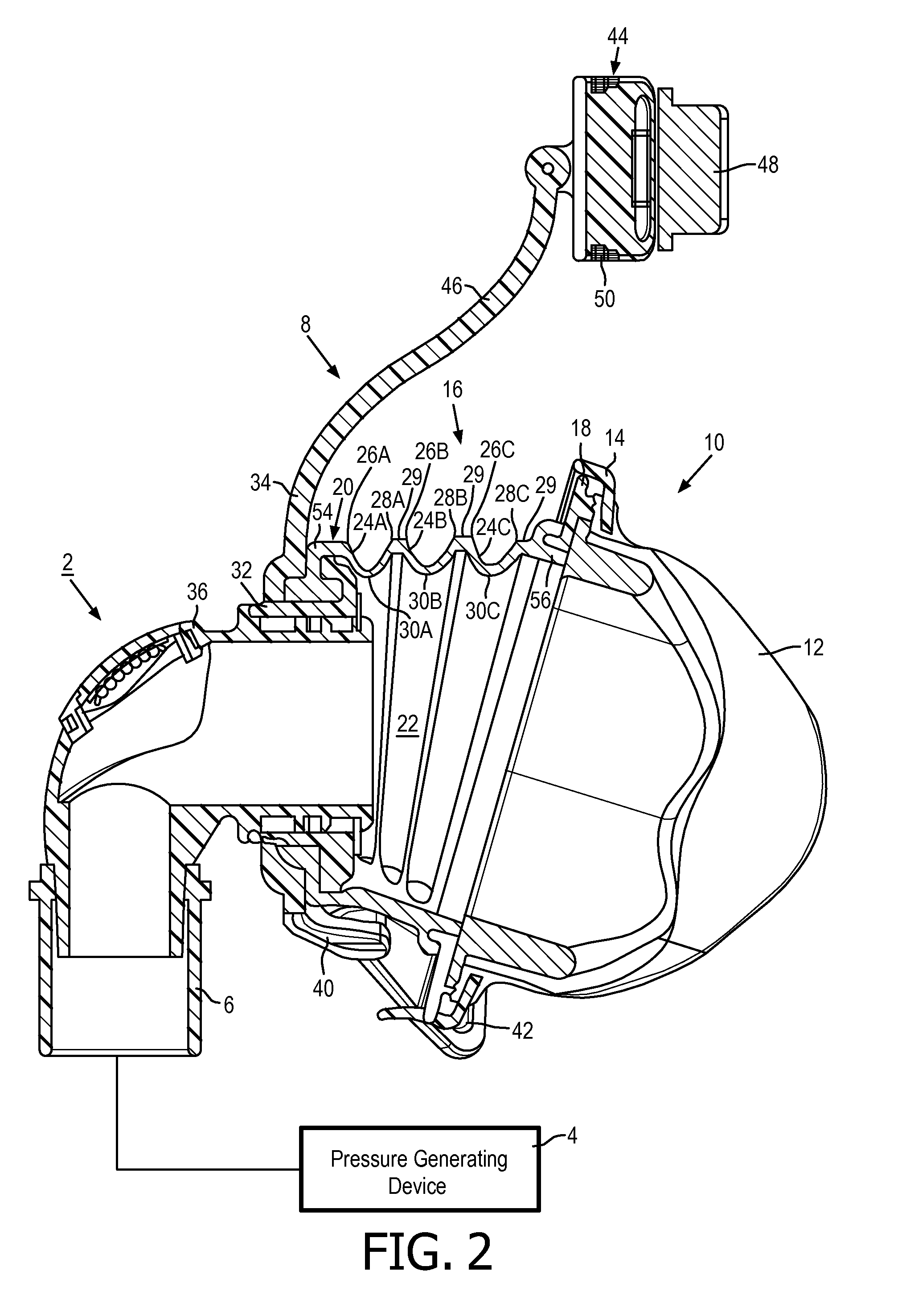
A patient interface device (8, 8′) for delivering a flow of breathing gas to an airway of a patient includes a grooved adjustment mechanism (20, 58, 78) having a main body (22, 60) formed from an elastic material, the main body having an outer surface having a plurality of convolutions (80) provided therein. Each convolution including a groove (24, 62, 84), and each convolution has a stiffness associated therewith. The stiffnesses associated with the convolutions increase from a first side of the main body to a second side of the main body.

Description

CROSS-REFERENCE TO RELATED APPLICATIONS[0001]This application claims the priority benefit under 35 U.S.C. §119(e) of U.S. Provisional Application No. 61 / 371,869 filed on Aug. 9, 2010, the contents of which are herein incorporated by reference.BACKGROUND OF THE INVENTION[0002]1. Field of the Invention[0003]The present invention relates to patient interface devices for transporting a gas to and / or from an airway of a user, and in particular, to a patient interface device including a dynamic self adjustment mechanism for adjusting, for example and without limitation, mask position and / or pressure.[0004]2. Description of the Related Art[0005]There are numerous situations where it is necessary or desirable to deliver a flow of breathing gas non-invasively to the airway of a patient, i.e., without intubating the patient or surgically inserting a tracheal tube in their esophagus. For example, it is known to ventilate a patient using a technique known as non-invasive ventilation. It is also...

Claims


Application Information

Patent Timeline
Patent Type & Authority Applications(United States)
IPC IPC(8): A61M16/06
CPCA61M16/06A61M16/0638A61M16/0611A61M16/0666A61M16/0644
Inventor STARTARE, ANTHONY VINCENTBAFILE, ANTHONY JONCIOCCIO, CHRISTOPHER ADAMSMITH, DAVIDHO, PETER CHI FAI
Owner KONINKLIJKE PHILIPS ELECTRONICS NV
Why Eureka
Try Eureka