Unlock instant, AI-driven research and patent intelligence for your innovation.
Coupling system including a safety fastener device
Active Publication Date: 2013-05-30
SAFRAN HELICOPTER ENGINES
View PDF6 Cites 0 Cited by
Summary
Abstract
Description
Claims
Application Information
AI Technical Summary
This helps you quickly interpret patents by identifying the three key elements:
Problems solved by technology
Method used
Benefits of technology
Benefits of technology
The present invention provides a safercoupling system that ensures the fluid supply continues even if the fastening connection is damaged or breaks. The system includes a safety fastener in the form of a sleeve that surrounds the fastening connection and is designed to engage with the coupling to provide fastening in case of a damage to the connection. This fastening prevents fluid leakage and ensures safe fluid supply.
Problems solved by technology
It is also well known that the fastening connection of a coupling mounted on a turbine engine is subjected to severe mechanical stresses because of the vibration generated by the turbine engine in operation, which can have harmful consequences leading to the fastening connection being damaged and to the junction breaking.
Pipe redundancy nevertheless presents various drawbacks such as cost, additional weight, bulk, and maintenance.
Method used
Image
Click on the blue label to locate the original text in one second.
Reading with bidirectional positioning of images and text.
Examples
first embodiment
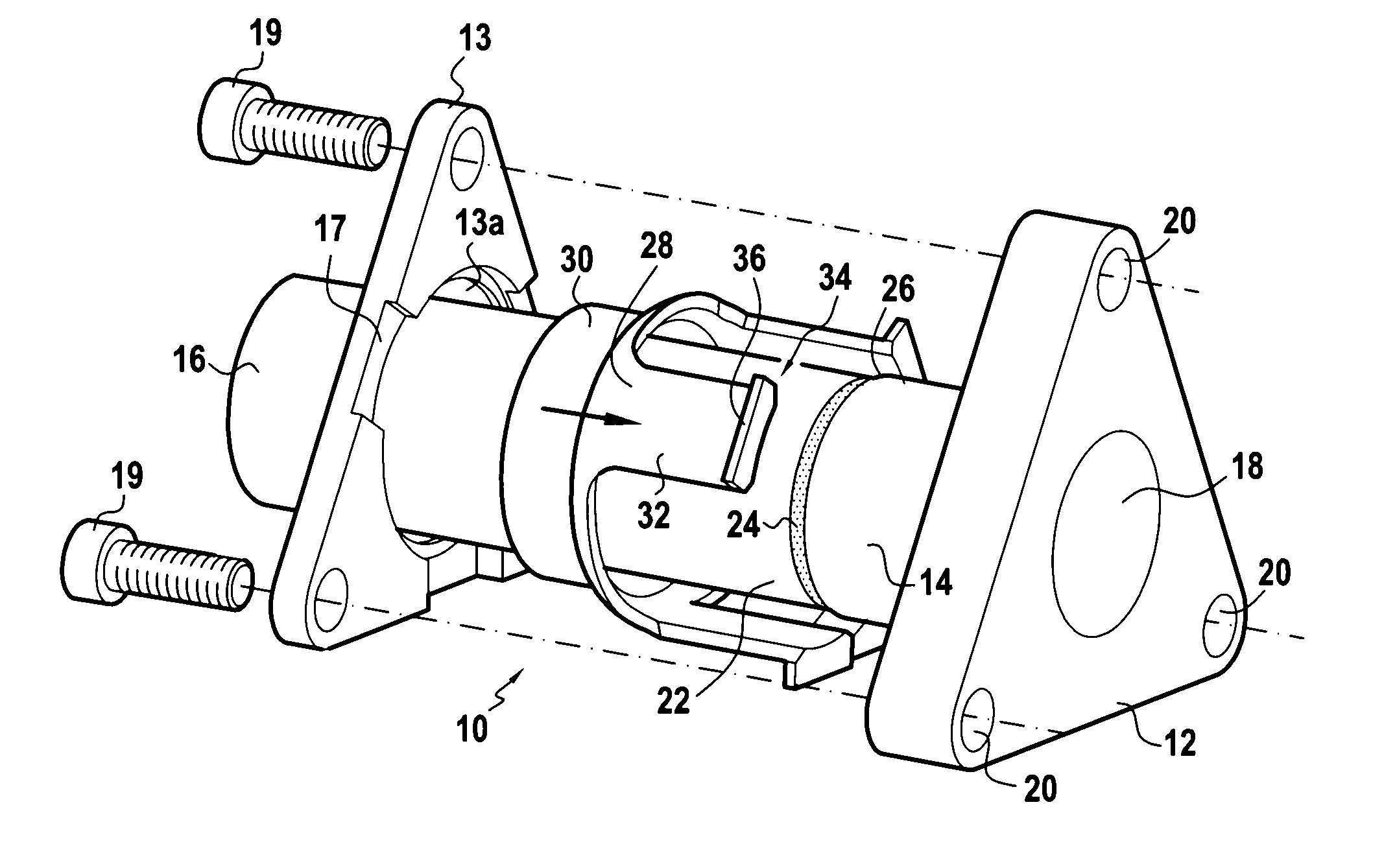
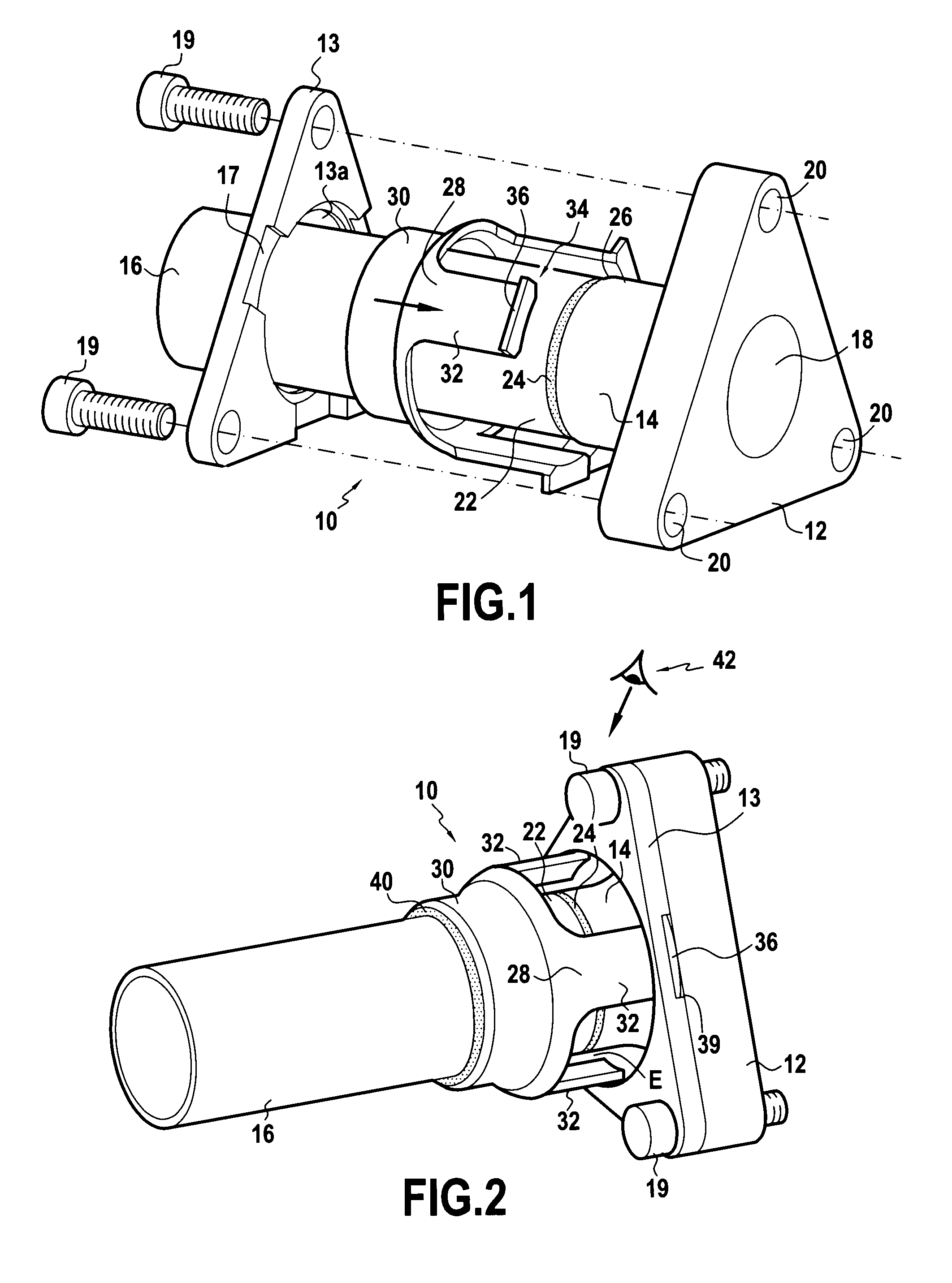
[0054]With reference to FIGS. 1 and 2, a coupling system 10 constituting the invention is described.
[0055]The coupling system 10 comprises a coupling 12 from which there extends a hollow cylindrical portion 14, which portion is to engage on a pipe 16 to make the connection between the coupling system 10 and the pipe 16.
[0056]Specifically, the coupling 12 is triangular in shape with rounded corners. Nevertheless, it is possible to provide some other shape without going beyond the ambit of the present invention.
[0057]The coupling 12 has a bore 18 passing therethrough and communicating coaxially with the hollow cylindrical portion 14.
[0058]As can be seen in FIG. 1, the coupling 12 has a plurality of orifices 20 for enabling the coupling 12 to be mounted on the member that is to be fed with compressed air, for example to a casing of the turbine engine.
[0059]With reference to FIGS. 1 and 2, it can be seen that the coupling 12 is for fastening to one end 22 of the pipe 16 via a fastening ...
second embodiment
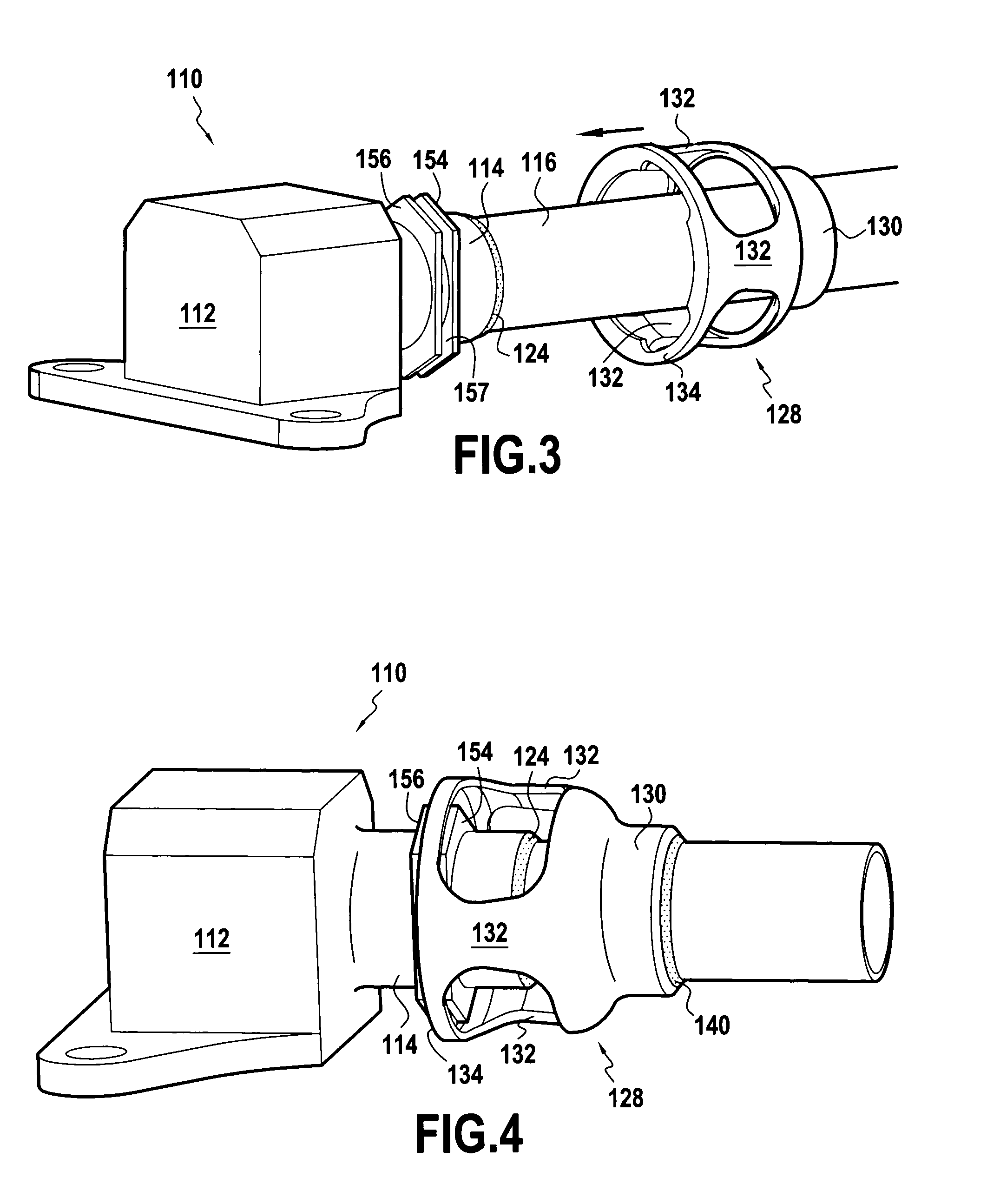
[0081]An advantageous second embodiment of a coupling system 110 of the present invention is described below with reference to FIGS. 3 to 6.
[0082]Elements in the second embodiment that are identical to elements of the first embodiment are given the same numerical reference plus 100.
[0083]FIG. 3 shows the coupling system 110 which includes a right-angled coupling 112. In other words, the flow direction of the fluid entering the coupling 112 is at right angles to the flow direction of the fluid leaving the coupling. The device of the invention can be applied regardless of the value of this angle.
[0084]As in the first embodiment, a hollow cylindrical portion 114 for engaging on the end of a pipe 116 extends from the coupling 112.
[0085]The coupling 112 and the pipe 116 are for fastening together by means of a fastening connection 124 forming an annular weld.
[0086]In accordance with the invention, the coupling system 110 further includes safety fastener means 128 forming a sleeve. The sl...
PUM
Abstract
A couplingsystem including a coupling for fastening to one end of a pipe via a fastening connection; and a sleeve surrounding the fastening connection is disclosed. The sleeve includes a first end for welding to the pipe, and a hook-forming second end for co-operating with the coupling in such a manner that the hook is suitable for providing fastening between the coupling and the pipe in the event of the fastening connection being damaged.
Description
[0001]The present invention relates to the field of pipe coupling systems used particularly, but not exclusively, in a helicopter turbine engine.BACKGROUND OF THE INVENTION[0002]The present invention relates more particularly to a coupling system comprising a coupling for fastening to one end of a pipe via a fastening connection.[0003]Conventionally, such a coupling system enables the pipe to be coupled to a member of the turbine engine for the purpose of feeding the member with a fluid, such a liquid or a gas, e.g. for the purpose of delivering compressed air to hot portions of the turbine engine in order to cool them.[0004]It is also well known that the fastening connection of a coupling mounted on a turbine engine is subjected to severe mechanical stresses because of the vibration generated by the turbine engine in operation, which can have harmful consequences leading to the fastening connection being damaged and to the junction breaking.[0005]To reduce the risk of such breakage...
Claims
Application Information
Patent Timeline
Application Date:The date an application was filed.
Publication Date:The date a patent or application was officially published.
First Publication Date:The earliest publication date of a patent with the same application number.
Issue Date:Publication date of the patent grant document.
PCT Entry Date:The Entry date of PCT National Phase.
Estimated Expiry Date:The statutory expiry date of a patent right according to the Patent Law, and it is the longest term of protection that the patent right can achieve without the termination of the patent right due to other reasons(Term extension factor has been taken into account ).
Invalid Date:Actual expiry date is based on effective date or publication date of legal transaction data of invalid patent.
IPC IPC(8): F16L13/02
CPCF16L13/06F16L13/02F16L35/00F16L23/024
Inventor AUZIAS, BENOIT MICHEL BERNARD VINCENTCRIADO, FRANCIS JEANSENGER, GERALD ANDRE CHARLES
