
Universal-Voltage Self-Heating Thermal Detector

Inactive Publication Date: 2013-05-30
LUTRON TECH CO LLC
View PDF5 Cites 6 Cited by
  • Summary
  • Abstract
  • Description
  • Claims
  • Application Information

AI Technical Summary

Benefits of technology

The present invention relates to a self-heating thermal protector for disconnecting an electrical load from an AC power source when insulation is present around the insulation detector independent of the magnitude of the AC mains line voltage. The thermal protector comprises a thermally-conductive enclosure, a temperature-sensitive switch, and a constant power circuit. The temperature-sensitive switch is located inside the enclosure and is adapted to be conductive and non-conductive in response to an internal temperature inside the enclosure. The constant power circuit dissipates a constant amount of power independent of the magnitude of the AC mains line voltage when the temperature-sensitive switch is conductive. The thermal protector is designed to protect against overcurrent or overvoltage events that could cause damage to the load or the AC power source. The lighting fixture also includes a load regulation device and a self-heating thermal protector for safely and efficiently controlling the power supplied to the load.

Problems solved by technology

However, prior art insulation detectors, such as the one described in the '884 patent, are only rated to operate with a specific AC mains line voltage (e.g., at either 120 V or 277 V).
This, of course, leads to additional stock keeping units (SKUs) and increased inventory cost for the lighting fixture manufacturer.

Method used


Image

  • Universal-Voltage Self-Heating Thermal Detector
  • Universal-Voltage Self-Heating Thermal Detector
  • Universal-Voltage Self-Heating Thermal Detector

Examples


Embodiment Construction

[0019]The foregoing summary, as well as the following detailed description of the preferred embodiments, is better understood when read in conjunction with the appended drawings. For the purposes of illustrating the invention, there is shown in the drawings an embodiment that is presently preferred, in which like numerals represent similar parts throughout the several views of the drawings, it being understood, however, that the invention is not limited to the specific methods and instrumentalities disclosed.

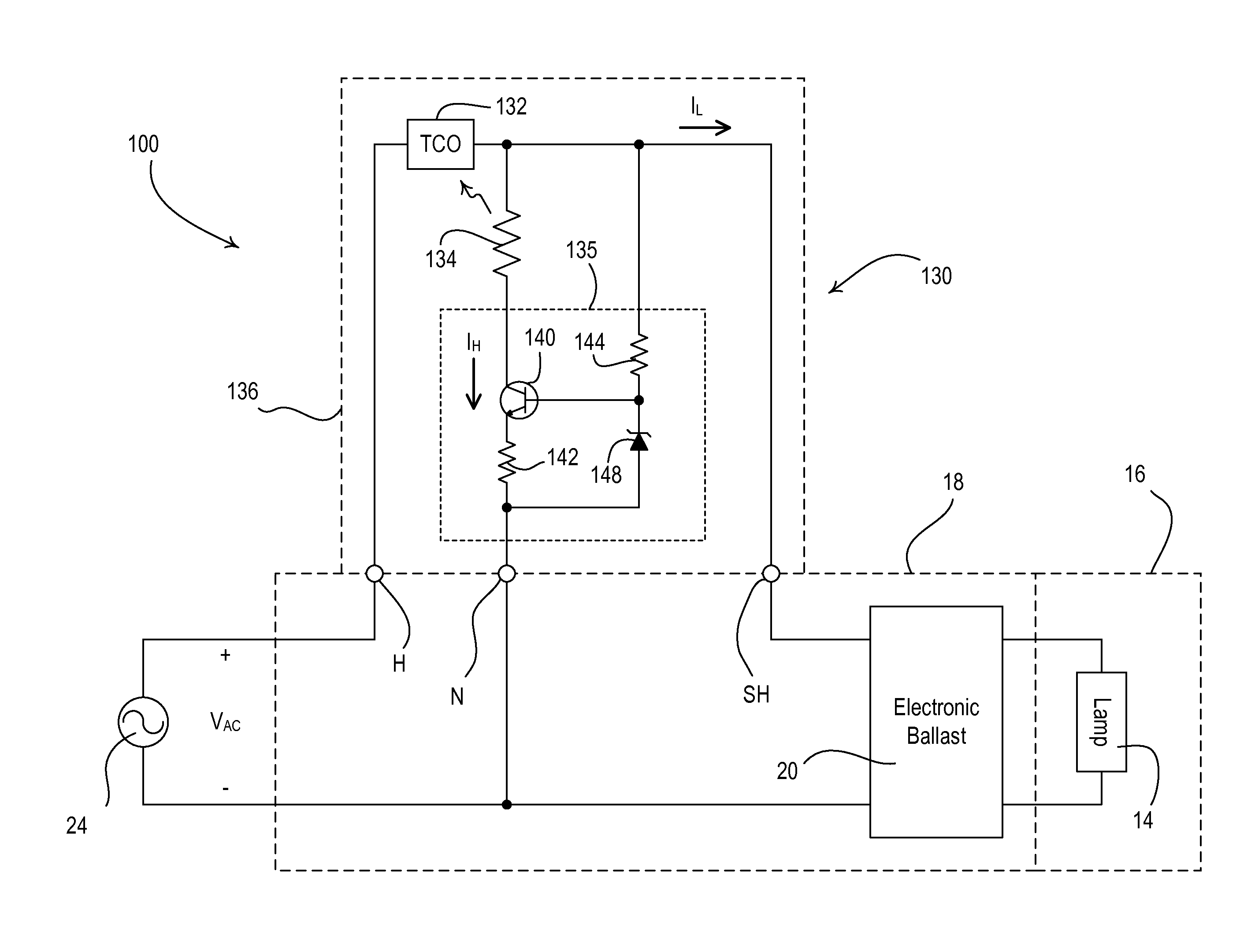
[0020]FIG. 3 is a simplified schematic diagram of a downlight fixture 100 having a universal-voltage self-heating thermal detector 130 (i.e., an insulation detector) according to an embodiment of the present invention. The thermal detector 130 comprises a temperature sensitive switch (such as, for example, a bimetallic switch or a TCO switch 132) coupled in series electrical connection between the hot terminal H and the switched hot terminal SH. The TCO switch 132 is operable to...


PUM


Abstract

A self-heating thermal protector operates to disconnect a load control device for a lighting load from an AC power source when insulation is present around the insulation detector independent of the magnitude of an AC mains line voltage of the AC power source. The insulation detector comprises a temperature-sensitive switch and a constant power circuit that are located in a thermally-conductive enclosure. The temperature-sensitive switch is coupled between the AC power source and the load control device and is rendered conductive and non-conductive in response to a temperature inside the enclosure. The constant power circuit is coupled in parallel with the AC power source and dissipates a constant amount of power independent of the magnitude of the AC mains line voltage when the temperature-sensitive switch is conductive. Restricted airflow over the thermal protector causes the temperature inside the enclosure to increase, such that the temperature-sensitive switch is rendered non-conductive.

Description

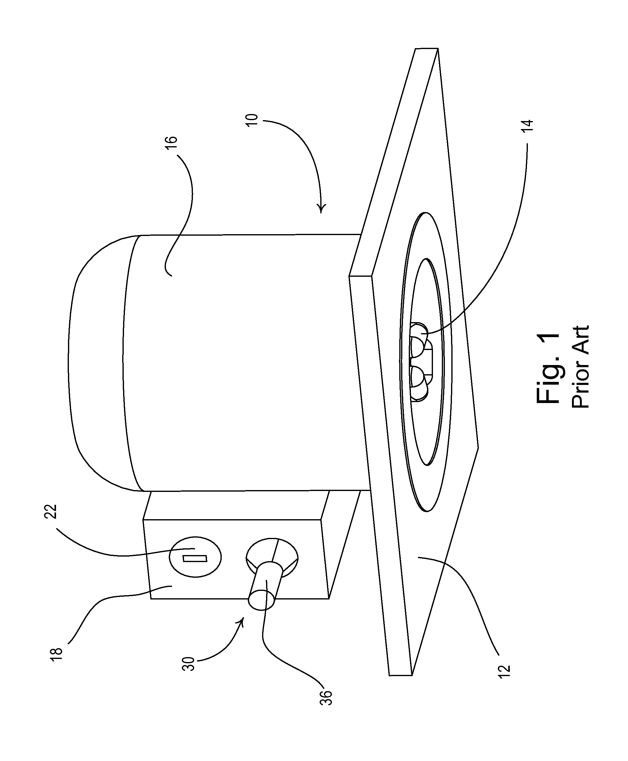
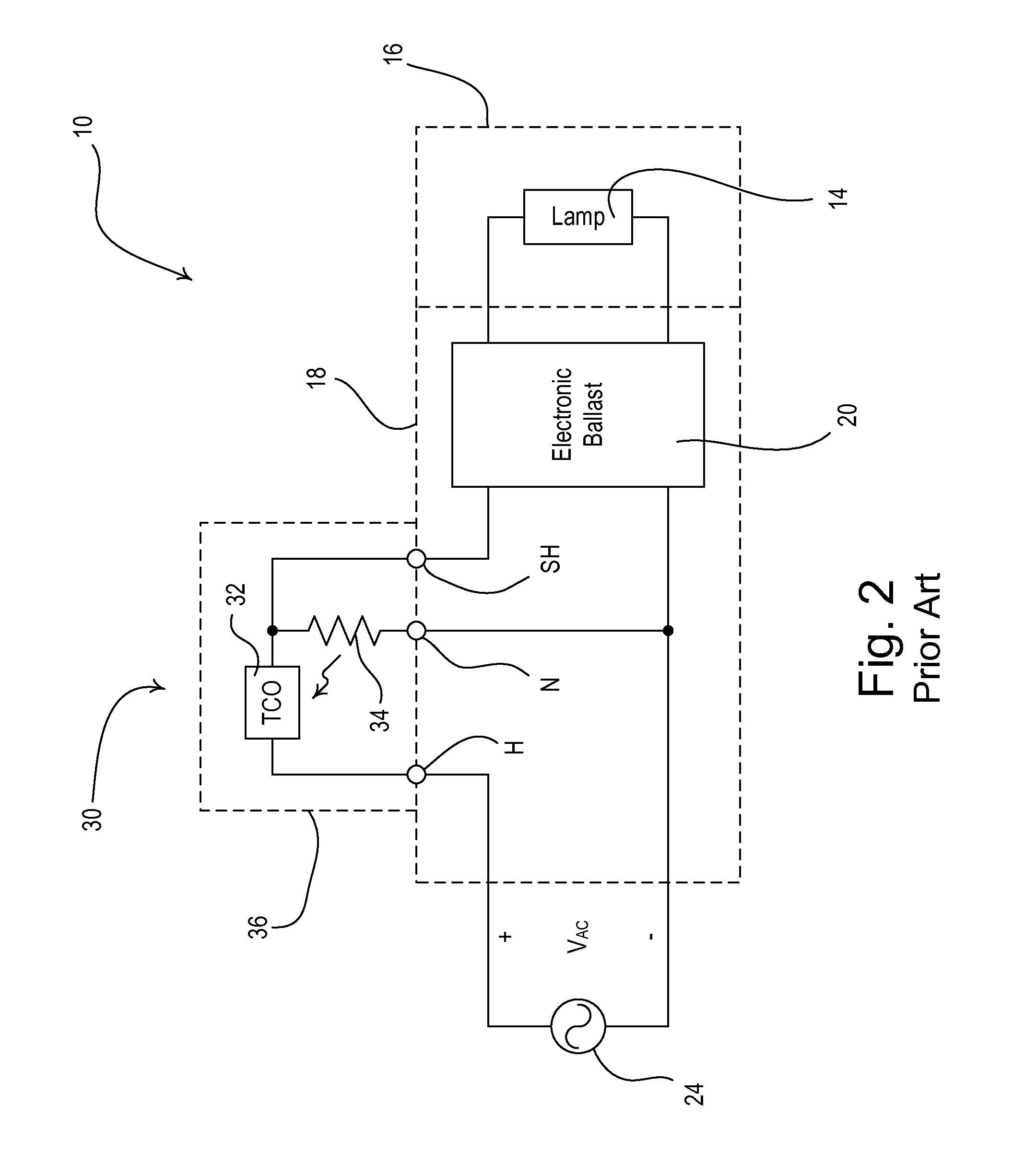
BACKGROUND OF THE INVENTION[0001]1. Field of the Invention[0002]The present invention relates to load control systems for controlling the power delivered from an alternating-current (AC) power source to an electrical load, and more particularly, to a universal-voltage insulation detector for a recessed downlight fixture having a lighting load, such as a fluorescent lamp or a light-emitting diode (LED) light source.[0003]2. Description of the Related Art[0004]Downlight fixtures are typically mounted to a ceiling and are often recessed into the ceiling to provide an aesthetically pleasing appearance. FIG. 1 is a perspective view of a prior art recessed downlight fixture 10, which may be mounted to a ceiling, for example, in a drop ceiling panel 12. The downlight fixture 10 comprises a lighting load, e.g., a compact fluorescent lamp 14, which is installed in a housing 16. The lighting load could alternatively comprise an incandescent lamp or a light-emitting diode (LED) light source (i...

Claims


Application Information

Patent Timeline
IPC IPC(8): H05B41/36H05B41/14H01H37/02H05B41/24
CPCH01H37/52F21V25/10Y02B20/341H05B33/089H05B41/2856F21S8/02Y02B20/00Y02B20/30H05B45/56
Inventor NUHFER, MATTHEW W.SHEARER, THOMAS M.
Owner LUTRON TECH CO LLC
Learn More