Unlock instant, AI-driven research and patent intelligence for your innovation.

Video encoding method, video decoding method, video encoding apparatus, video decoding apparatus, and program thereof

a video encoding and video encoding technology, applied in the direction of color television with bandwidth reduction, signal generator with optical-mechanical scanning, signal generation, etc., can solve the problems of significant calculation complexity, low filter performance, and limitation in performance improvement in terms of coding efficiency, so as to improve coding efficiency and reduce prediction error energy

Inactive Publication Date: 2013-05-30
NIPPON TELEGRAPH & TELEPHONE CORP
View PDF3 Cites 8 Cited by
  • Summary
  • Abstract
  • Description
  • Claims
  • Application Information

AI Technical Summary

Benefits of technology

The present invention allows for better division of regions in images and uses interpolation filters that consider the spatiotemporal locality of the image. This results in improved coding efficiency and reduced prediction error energy.

Problems solved by technology

However, in acquiring ¼ precision pixels, the performance of the filter is not high.
Accordingly, there is considered to be a limitation in performance improvement in terms of the coding efficiency.
However, since the degree of calculation complexity is significantly high in acquiring the filter coefficients, a proposal for reducing the degree of calculation complexity is introduced in Non-Patent Document 5.

Method used


Image

  • Video encoding method, video decoding method, video encoding apparatus, video decoding apparatus, and program thereof
  • Video encoding method, video decoding method, video encoding apparatus, video decoding apparatus, and program thereof
  • Video encoding method, video decoding method, video encoding apparatus, video decoding apparatus, and program thereof

Examples


Embodiment Construction

[0078]Hereinafter, an embodiment of the present invention will be described with reference to the accompanying drawings. In addition, as an example, a method for dividing a region in units of frames is described. However, the region may be divided in units of slices. Furthermore, region division may be decided in a plurality of frames such as two or three frames.

[0079][Video Encoding Apparatus]

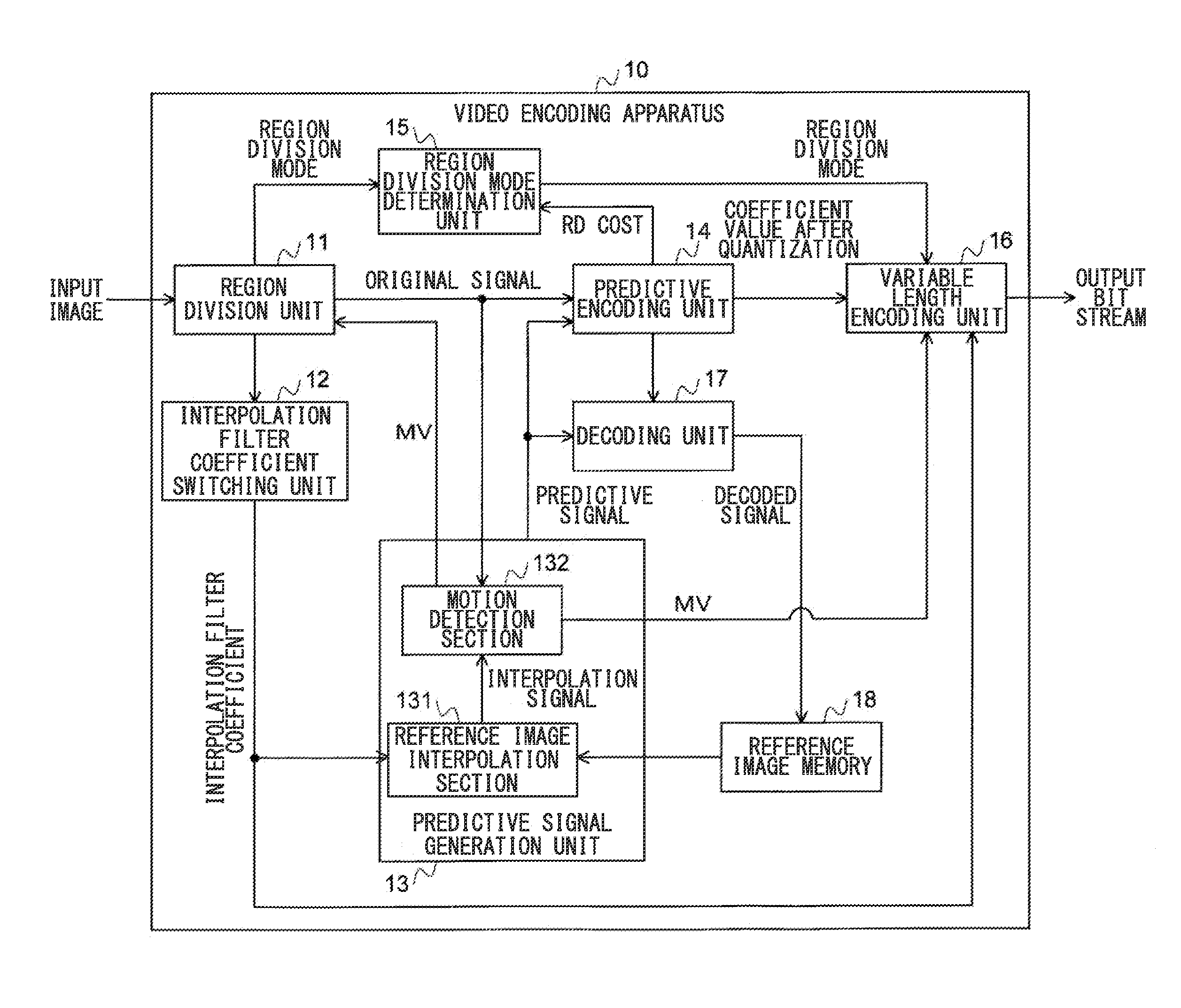
[0080]FIG. 1 is a diagram illustrating a configuration example of a video encoding apparatus in accordance with an embodiment of the present invention. A video encoding apparatus 10 divides a region using a plurality of region division schemes (called region division modes), performs interpolation of decimal precision pixels using a region division-type adaptive interpolation filter based on region division in which an encoding cost is minimized among respective region division modes, and performs encoding using decimal precision motion compensation. This video encoding apparatus is different ...


PUM


Abstract

A video encoding apparatus reduces residual energy of motion-compensated inter-frame prediction and improves the coding efficiency in encoding of an image in which optimal values of interpolation filter coefficients are changed in time and space. In the video encoding apparatus, a region division unit sequentially selects region division schemes one by one from among a plurality of prepared region division schemes, and divides a region of an image to be encoded. An interpolation filter coefficient switching unit switches interpolation filter coefficients of a decimal precision pixel for each divided region, and a predictive encoding unit performs predictive encoding. A region division mode decoding section selects a region division scheme, in which a cost is minimized among rate distortion costs calculated for each region division scheme. Using the selected region division scheme, the predictive encoding unit and a variable length encoding unit encode the image to be encoded. Information indicating the region division scheme is also subject to variable length encoding and is transmitted to a decoder.

Description

TECHNICAL FIELD[0001]The present invention relates to a video encoding method, a video decoding method, a video encoding apparatus, a video decoding apparatus, and a program thereof, which have a function of changing a set of interpolation filter coefficients within a frame.[0002]Priority is claimed on Japanese Patent Application No. 2010-180814, filed Aug. 12, 2010, the content of which is incorporated herein by reference.BACKGROUND ART[0003]According to video encoding, in inter-frame prediction (motion compensation) encoding in which prediction is performed between different frames, a motion vector is obtained with reference to an already decoded frame such that prediction error energy and the like are minimized. A residual signal generated by the motion vector is orthogonally transformed, is subject to quantization, and is generated as binary data through entropy encoding. In order to improve coding efficiency, it is necessary to obtain a prediction scheme with higher prediction ...

Claims


Application Information

Patent Timeline
IPC IPC(8): H04N7/26H04N19/50H04N19/117H04N19/137H04N19/139H04N19/147H04N19/154H04N19/174H04N19/196H04N19/46H04N19/463H04N19/503H04N19/51H04N19/523H04N19/553H04N19/59H04N19/70
CPCH04N19/00569H04N19/119H04N19/587H04N19/172H04N19/117H04N19/147
Inventor MATSUO, SHOHEIBANDOH, YUKIHIROTAKAMURA, SEISHIJOZAWA, HIROHISA
Owner NIPPON TELEGRAPH & TELEPHONE CORP