Buckling restrained brace

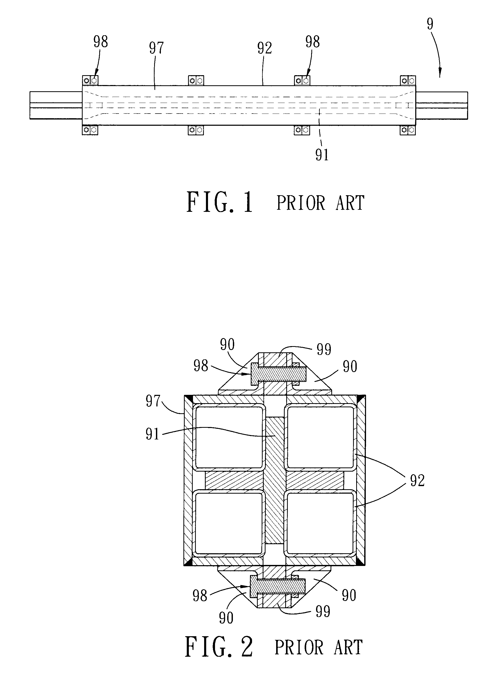
a buckling restraint and brace technology, applied in the direction of shock-proofing, load-supporting braces, building components, etc., can solve the problems of buckling restraint brace damage, having to be replaced by a new one, and the damage examination procedure of the conventional buckling restraint brace b>9/b> is still relatively troublesome, so as to achieve the effect of easy examination

Inactive Publication Date: 2013-06-06
NAT APPLIED RES LAB
View PDF9 Cites 28 Cited by
  • Summary
  • Abstract
  • Description
  • Claims
  • Application Information

AI Technical Summary

Benefits of technology

[0007]Therefore, the object of the present invention is to provide a buckling restrain

Problems solved by technology

However, once the restraining member is destroyed, the entire buckling restrained brace would be damaged and has to be replaced by a new one, regardless of whether the axial m

Method used


Image

  • Buckling restrained brace
  • Buckling restrained brace
  • Buckling restrained brace

Examples


Embodiment Construction

[0026]Before the present invention is described in greater detail, it should be noted that like elements are denoted by the same reference numerals throughout the disclosure.

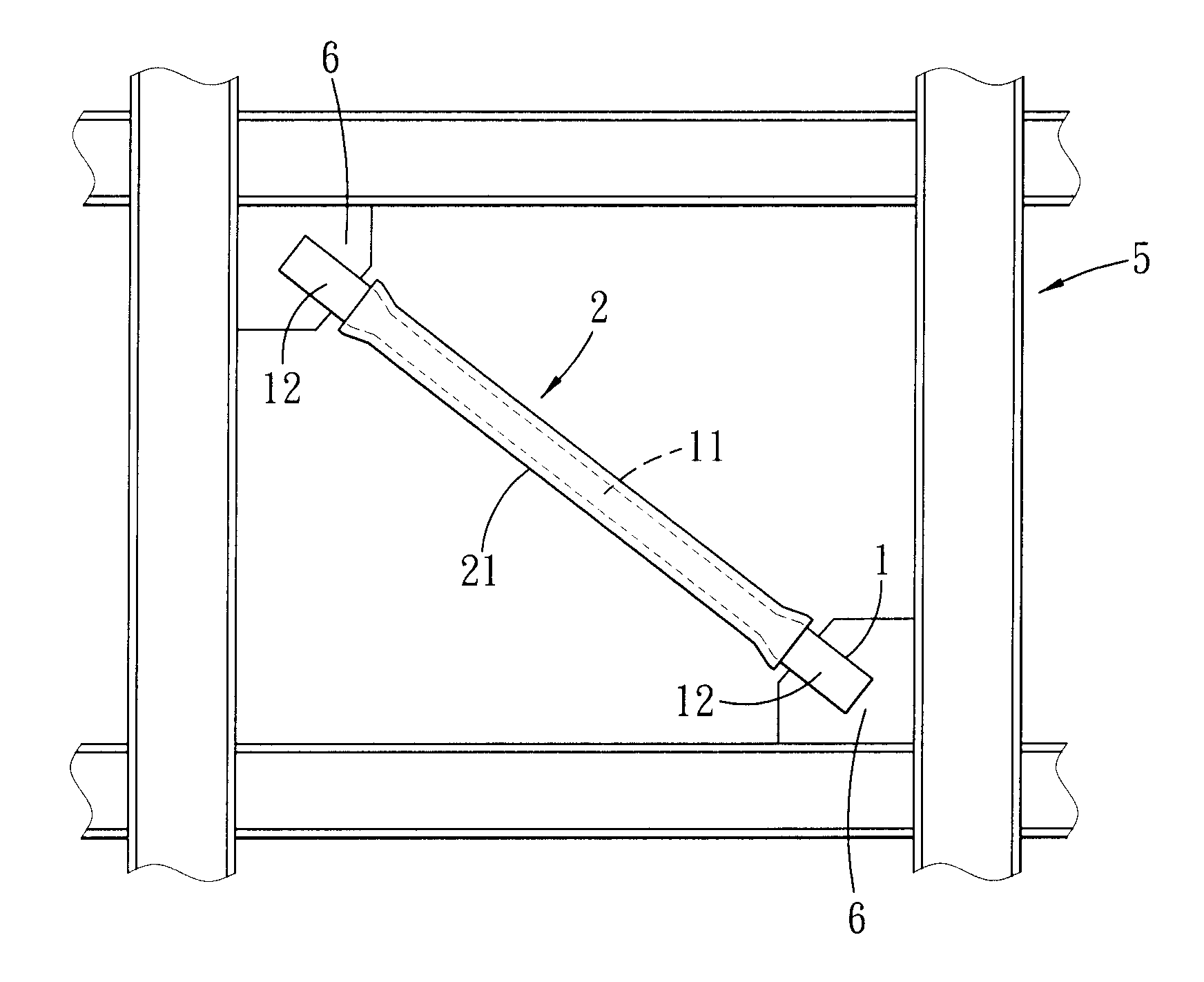
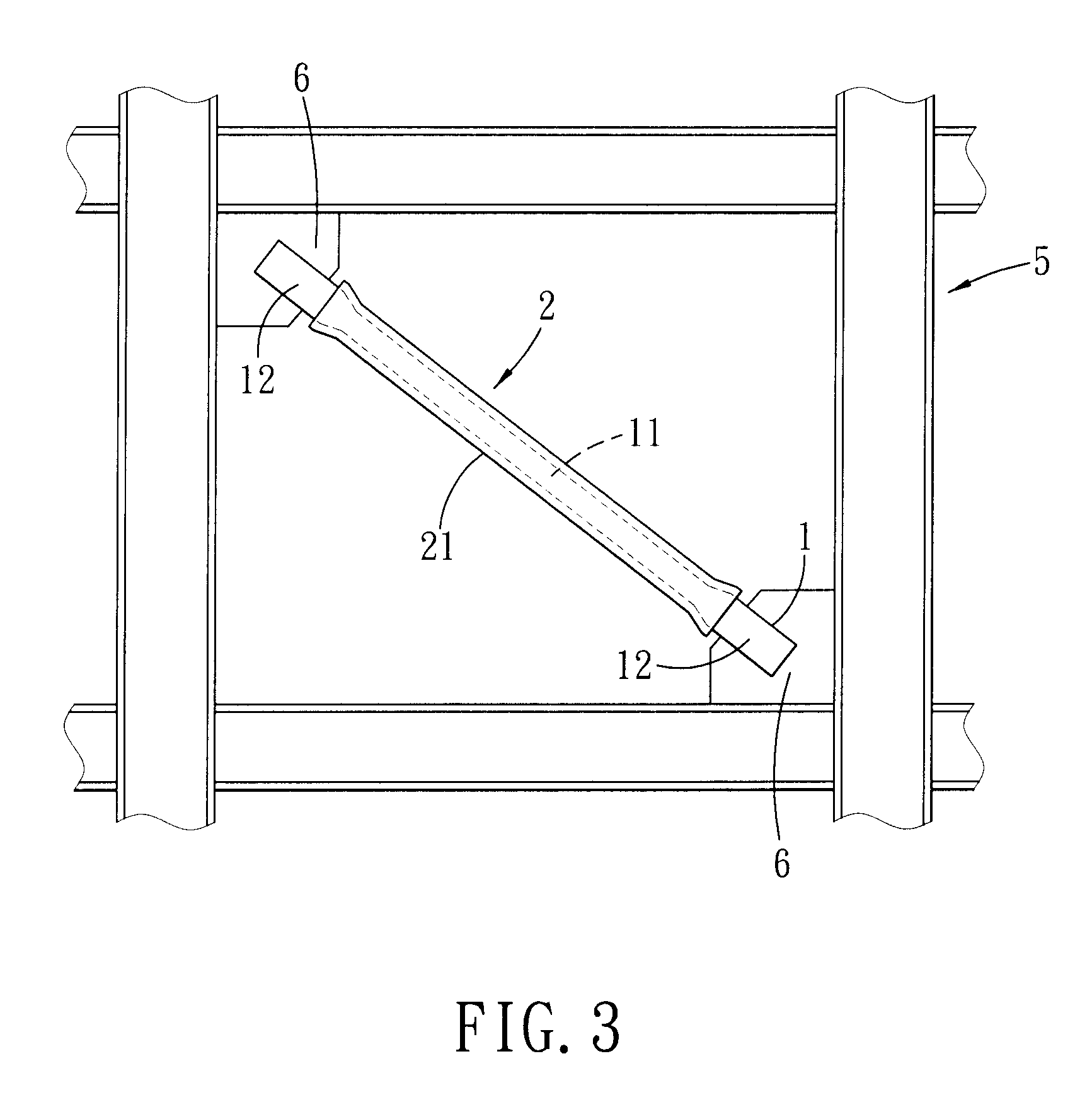
[0027]As shown in FIGS. 3 to 6, the first preferred embodiment of a buckling restrained brace according to the present invention is adapted to be connected fixedly between two connecting plates 6 of a framework 5 of a structure. The structure is, for example, a building, a bridge, a wharf, a dam, a tower, an electrical tower or a tunnel. The structure includes a structure body connected to the framework 5. In this embodiment, the structure is a building, and the structure body has a wall structure that includes a pair of spaced-apart wall plates 9 (only one is shown in FIG. 6). One of the wall plates 9 is formed with a through hole 92. The framework 5 and the buckling restrained brace of this invention are disposed between the wall plates 9. The buckling restrained brace comprises an axial member 1, a restrainin...


PUM


Abstract

A buckling restrained brace includes an axial member, a plurality of restraining members, and a plurality of securing units. The axial member includes a middle section extending in an axial direction, and two coupling sections extending respectively from opposite ends of the middle section and coupled fixedly to two connecting plates of a framework of a building. The restraining members extend in the axial direction and are disposed around and contact the axial member. Each securing unit secures an adjacent pair of the restraining members together. Each restraining member cooperates with an adjacent one of the restraining members to define an opening therebetween through which a portion of the axial member is exposed for viewing.

Description

CROSS-REFERENCE TO RELATED APPLICATION[0001]This application is a continuation-in-part (CIP) of co-pending U.S. patent application Ser. No. 13 / 106,397, filed on May 12, 2011, and abandoned as of the filing date of this application.BACKGROUND OF THE INVENTION[0002]1. Field of the Invention[0003]The invention relates to a buckling restrained brace, more particularly to a buckling restrained brace that includes an axial member visible from the outside of a wall structure in which the buckling restrained brace is embedded.[0004]2. Description of the Related Art[0005]Concentrically braced frames are generally used in a framework of a building for enhancing economically the lateral stiffness of the framework to resist lateral force of an earthquake. A buckling restrained brace, which is a kind of the concentrically braced frames, is particularly configured to have a relatively full hysteresis loop for effectively absorbing vibration energy generated by the earthquake so as to minimize dam...

Claims


Application Information

Patent Timeline
IPC IPC(8): E04B1/98E04B1/19
CPCE04B1/98E04B1/1903E04C2003/026E04H9/028E04H9/02E04H9/0237
Inventor TSAI, KEH-CHYUANWU, AN-CHIENWEI, CHIH-YULIN, PAO-CHUN
Owner NAT APPLIED RES LAB
Why Eureka
Try Eureka