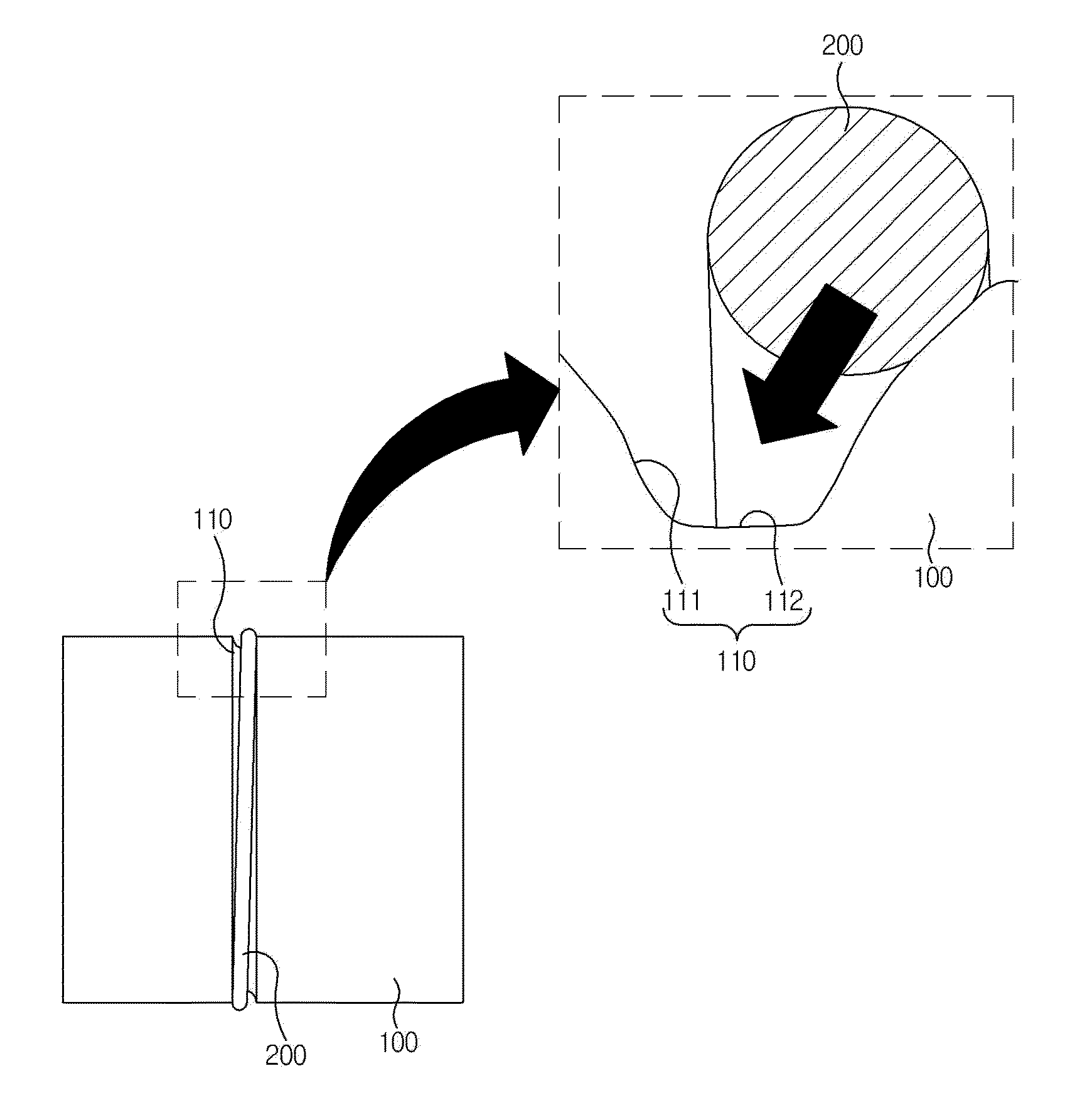
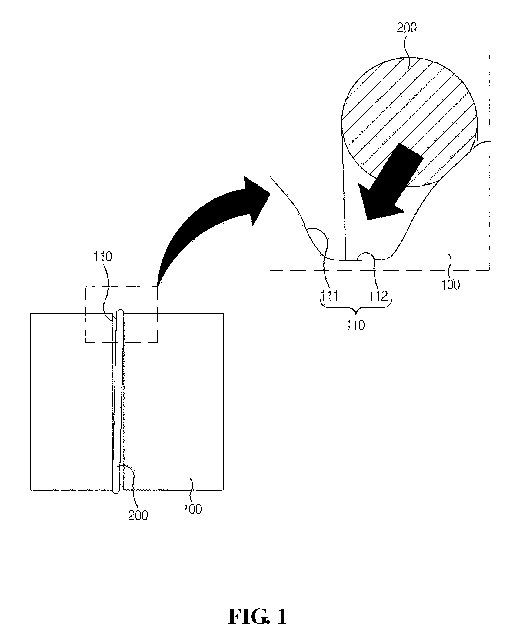
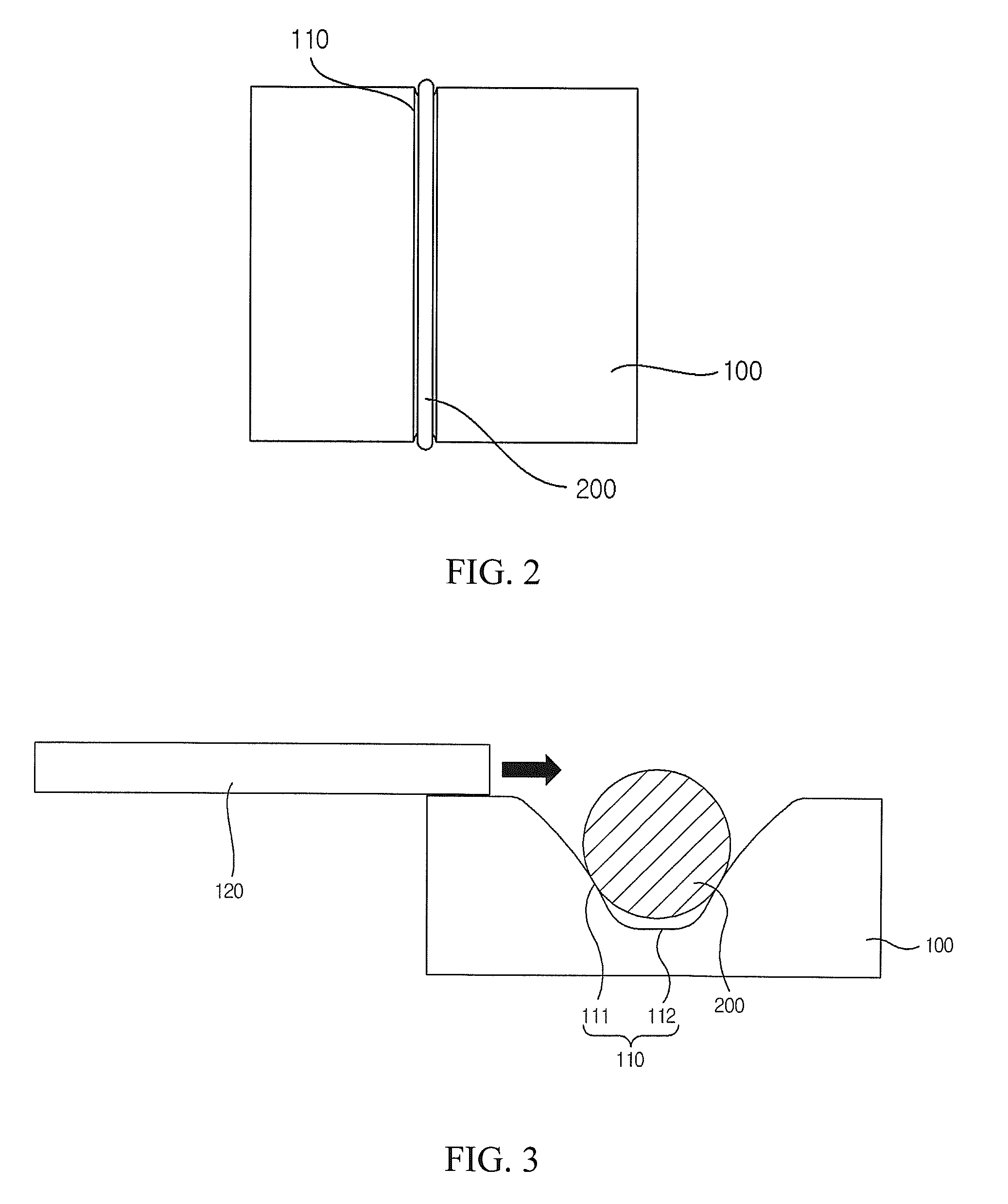
Recess for o-ring

a technology of o-rings and o-rings, which is applied in the direction of washing machines, couplings, manufacturing tools, etc., can solve the problems of difficult to maintain the intended or designed fluid tightness by using the o-rings, and the o-rings may often deviate from the original location, so as to achieve the effect of maintaining fluid tightness

Inactive Publication Date: 2013-06-06
LG INNOTEK CO LTD
View PDF10 Cites 1 Cited by
  • Summary
  • Abstract
  • Description
  • Claims
  • Application Information

AI Technical Summary

Benefits of technology

[0026]The O-ring insertion recess according to the present disclosure has an advantageous effect in that, in a case a first part mounted with the O-ring is coupled to a second part, the O-ring interfering with the second part is deformed in response to insertion operation of the second part to form a curved wall surface on both the contacted wall surface and a wall surface opposite to the contacted wall surface, such that even if the O-ring is assembled in a state where the O-ring is deviated from an original location, the first and second parts are coupled to enable maintenance of fluid tightness when the O-ring is compressed, and a space in which the O-ring is deformed can be increased to maintain a maximally fluid tight sealed state between the first and second parts.

Problems solved by technology

However, in a case the recess for insertion of O-ring is formed in a shape having a square cross-section at a floor surface, the O-ring may frequently deviate from an original location when a pressure is applied to a sealing unit which is assembled on an opposite part using the O-ring.
In a case the O-ring is deviated from the original location, problems arise that it is difficult to maintain an intended or designed fluid tightness by using the O-ring.

Method used


Image

  • Recess for o-ring
  • Recess for o-ring
  • Recess for o-ring

Examples


Embodiment Construction

[0035]Advantages and features of the present disclosure may be understood more readily by reference to the following detailed description of exemplary embodiments and the accompanying drawings. Detailed descriptions of well-known functions, configurations or constructions are omitted for brevity and clarity so as not to obscure the description of the present disclosure with unnecessary detail. Thus, the present disclosure is not limited to the exemplary embodiments which will be described below, but may be implemented in other forms. In the drawings, the width, length, thickness, etc. of components may be exaggerated or reduced for the sake of convenience. Furthermore, throughout the descriptions, the same reference numerals will be assigned to the same elements in the explanations of the figures, and explanations that duplicate one another will be omitted. Accordingly, the meaning of specific terms or words used in the specification and claims should not be limited to the literal o...


PUM


Abstract

Disclosed is a recess for O-ring, the recess including both lateral walls facing the O-ring formed each in a convexly curved shape toward the O-ring, and a floor surface connected to the curved lateral walls, wherein each of the curved lateral walls and the floor surface is formed at a first part to have a depth smaller than a diameter of the O-ring, and a surface facing a second part opposite to the first part is opened.

Description

CROSS-REFERENCE TO RELATED APPLICATION[0001]The present application is based on, and claims priority from the Korean Application Number 10-2011-0127509, filed on Dec. 1, 2011, the disclosure of which is incorporated by reference herein in its entirety.BACKGROUND[0002]1. Field of the Disclosure[0003]The present disclosure relates to a recess for inserting an O-ring.[0004]2. Discussion of the Related Art[0005]This section provides background information related to the present disclosure which is not necessarily prior art.[0006]Generally,[0007]An O-ring, which functions as a sealing member, is disposed in an annular recess to provide a sealing engagement and / or to form a fluid tight seal at a coupled area between two different parts. At this time, a recess is generally provided to accommodate and to restrict the O-ring at a predetermined position. The recess may be provided in a shape corresponding to that of the O-ring or in a shape flat in a floor surface.[0008]However, in a case the...

Claims


Application Information

Patent Timeline
Patent Type & Authority Applications(United States)
IPC IPC(8): F16L21/02
CPCY10T403/52F16J15/062F16B2200/60F16J15/02F16K5/06
Inventor RYU, WOONGSEON
Owner LG INNOTEK CO LTD
Why Eureka
Try Eureka