A controllable float module, a modular offshore structure assembly comprising at least one controllable float module and a method for assembling a modular offshore structure in situ

a technology of controllable float modules and offshore structures, which is applied in the direction of wind energy generation, vessel construction, vessel movement reduction by mass displacement, etc., to achieve the effects of low availability, low day rate charges, and low dra

Active Publication Date: 2018-10-25
HARDCASTLE TREVOR M
View PDF0 Cites 3 Cited by
  • Summary
  • Abstract
  • Description
  • Claims
  • Application Information

AI Technical Summary

Benefits of technology

[0018]The addition of the wind turbine is made by changing the buoyancy of the floating structure to take advantage of the ‘semi-submersible’ design, which can be de-ballasted allowing a very shallow draft. This feature allows the floating structure to be towed back to a quayside where conventional mobile heavy lift crane can assemble the wind turbine tower sections, nacelle, rotor and blades onto the floating structure. This obviates the need for

Problems solved by technology

Currently this is not the case with other forms of fl

Method used


Image

  • A controllable float module, a modular offshore structure assembly comprising at least one controllable float module and a method for assembling a modular offshore structure in situ
  • A controllable float module, a modular offshore structure assembly comprising at least one controllable float module and a method for assembling a modular offshore structure in situ
  • A controllable float module, a modular offshore structure assembly comprising at least one controllable float module and a method for assembling a modular offshore structure in situ

Examples


Embodiment Construction

)

[0061]The exemplary embodiments of this invention will be described in relation to an offshore support structure for an offshore wind farm that is suitable for intermodal containerised freight transport. However, it is understood by a person skilled in the art that the controllable float module and / or modular offshore support structure assembly may equally be applicable to any other suitable offshore structure and / or equipment.

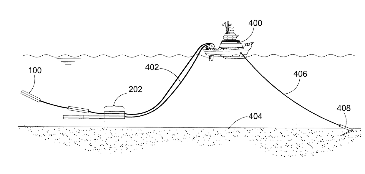
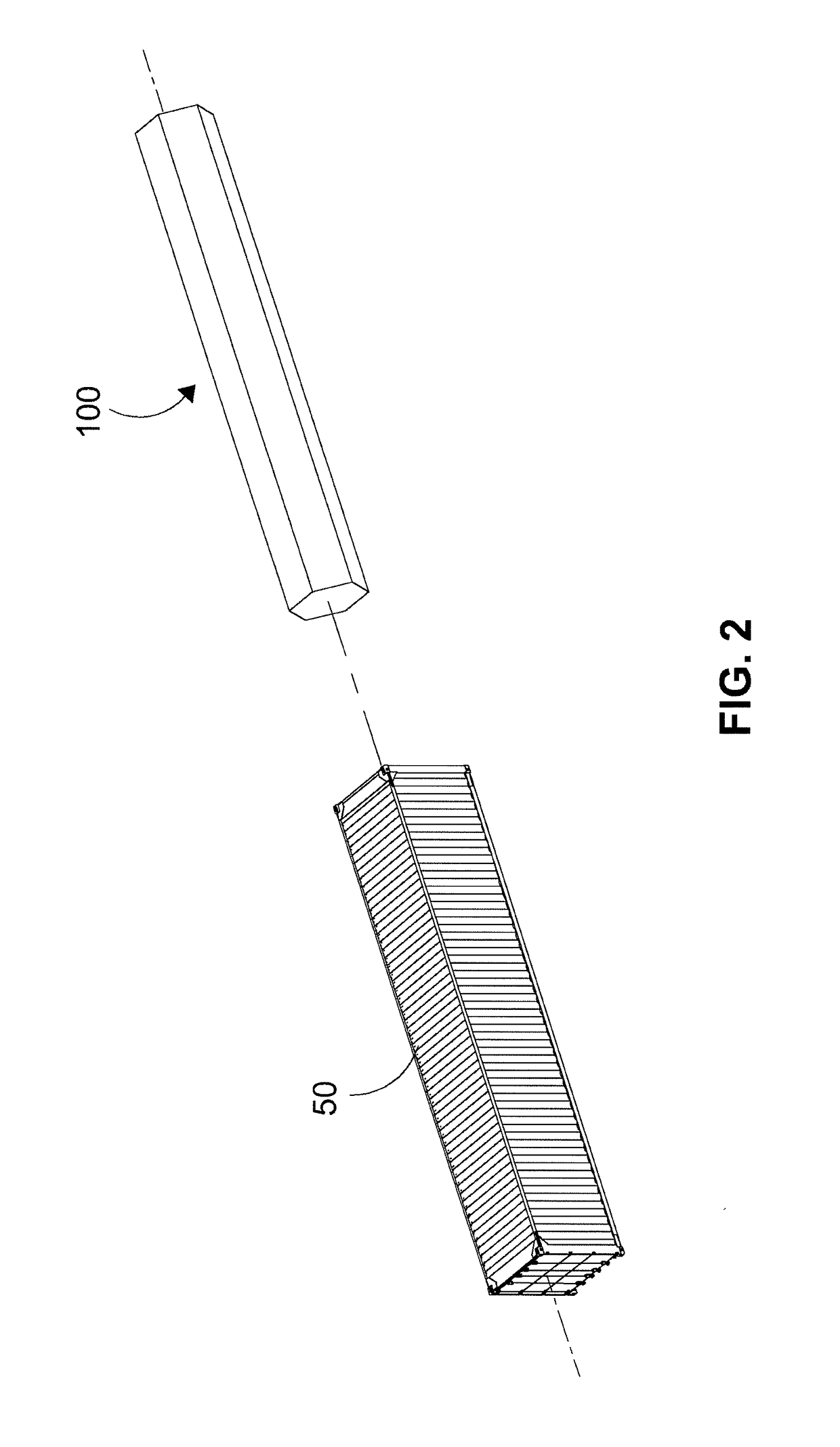
[0062]The invention is a Modular floating support structure 200 suitable for Intermodal Containerised Transport, that obviates or eliminates the requirement to use a floodable dock, slipway or similar facility normally necessary for construction of a floating support structure. In particular, the invention consists of one or more controllable float modules 100 that are assemblable to form the floating support structure 200. The controllable float modules 100 can be manufactured in a centralised plant or in a number of plants, but not necessarily at a coastal ...


PUM


Abstract

The present invention provides a controllable float module for a modular offshore support structure assembly. The inventive float module comprises (i) a first ballast chamber provided within a predetermined first portion of said float module, having at least one first controllable fluid connection, adapted to provide controlled fluid flow between an interior of said first ballast chamber and a first fluid reservoir containing a first fluid, and at least one second fluid connection, adapted to provide controlled fluid flow between said interior of said first ballast chamber and a second fluid reservoir containing a second fluid; (ii) at least one second ballast chamber provided within a predetermined second portion of said float module, having at least one first controllable fluid connection, adapted to provide controlled fluid flow between an interior of said second ballast chamber and said first fluid reservoir containing said first fluid, and at least one second fluid connection, adapted to provide controlled fluid flow between said interior of said second ballast chamber and said second fluid reservoir containing said second fluid, and (iii) a control system, adapted to control each of said at least one first and second controllable fluid connection and selectively vary the proportional quantity of said first fluid and said second fluid within any one of said first and at least one second ballast chamber, so as to selectively vary the buoyancy of any one of said at least one predetermined first and second portion of said float module when in use.

Description

[0001]The present invention generally relates to offshore floating support structures, and in particular to a modular floating structure that is assemblable at the location of operation either manually or via remote control.INTRODUCTION[0002]Requirement for Renewable Energy:[0003]The need for renewable electrical energy generation to substitute fossil-fuelled generation is a challenge now faced by almost two-hundred nations following the United Nations led Global Climate summit held in Paris in December 2015. A pact was declared as ‘adopted’ by the nations by the French Foreign Minister Laurent Fabius on 11 Dec. 2015. The pact agreed is to meet the target of no more than 1.5° C. (degrees centigrade) temperature rise, previously 2° C., and consequently there is a need to more swiftly introduce significant capacity of renewable energy generation.[0004]Offshore Wind Power Generation:[0005]Offshore wind power generation has been identified as a viable solution to eliminate carbon dioxid...

Claims


Application Information

Patent Timeline
IPC IPC(8): B63B9/06B63B39/03B63B35/44
CPCB63B9/065B63B39/03B63B35/44B63B2009/067B63B2035/446B63B75/00B63B77/10Y02E10/727B63B2209/20
Inventor HARDCASTLE, TREVOR M.
Owner HARDCASTLE TREVOR M
Why Eureka
Try Eureka