
Charger with Multi-sided Arrangement

a charging arrangement and multi-sided technology, applied in the field of chargers, can solve the problems of increasing the size of the charger, the inconvenient response of the charger, and the limited number of rechargeable batteries which can be simultaneously recharged, and achieve the effect of convenient respons

Inactive Publication Date: 2013-06-06
NEW WELL WEALTH CREATION
View PDF24 Cites 8 Cited by
  • Summary
  • Abstract
  • Description
  • Claims
  • Application Information

AI Technical Summary

Benefits of technology

The patent describes a charger with a multi-sided charging arrangement, which allows rechargeable batteries to be accommodated on multiple sides of the charger. This design makes it convenient and easy for users to retrieve batteries from the different sides. The charger can be attached and detached from the power source, preventing users from forgotten parts. The charger also has a separate housing for voltage conversion circuitry and charging circuitry, allowing for circuit amendments without additional costs. The technical effects of this patent include improved user experience, convenient and easy battery retrieval, and flexibility for manufacturers to respond to market changes without excessive costs.

Problems solved by technology

A major disadvantage for this type of conventional charger is that conventional chargers such as the one described above usually has one single charging side only.
Thus, the number of rechargeable batteries which can be simultaneously recharged is very limited because the single charging side can only have a limited area.
However, from the practical perspective, when the area of the charging side is increased, the overall size of the charger is also increased so that the charger will become very bulky and this substantially limits the range of applications of the charger.
This disadvantage has become particularly pressing when a charger needs to accommodate more than one type of rechargeable battery.
This unique requirement makes the structure of the rechargeable battery very complicated.
Another disadvantage of the above-mentioned conventional charger is that when a manufacturer wishes to get a predetermined certification from a recognized authority, such as the well-known Geprüfte Sicherheit or “GS” certification mark for product safety, the manufacturer must submit the entire electric circuit to the designated authority for examination.
This brings a substantial trouble to the manufacturer because varying market conditions may require slight amendments to an approved or certified electric circuit.

Method used


Image

  • Charger with Multi-sided Arrangement
  • Charger with Multi-sided Arrangement
  • Charger with Multi-sided Arrangement

Examples


Embodiment Construction

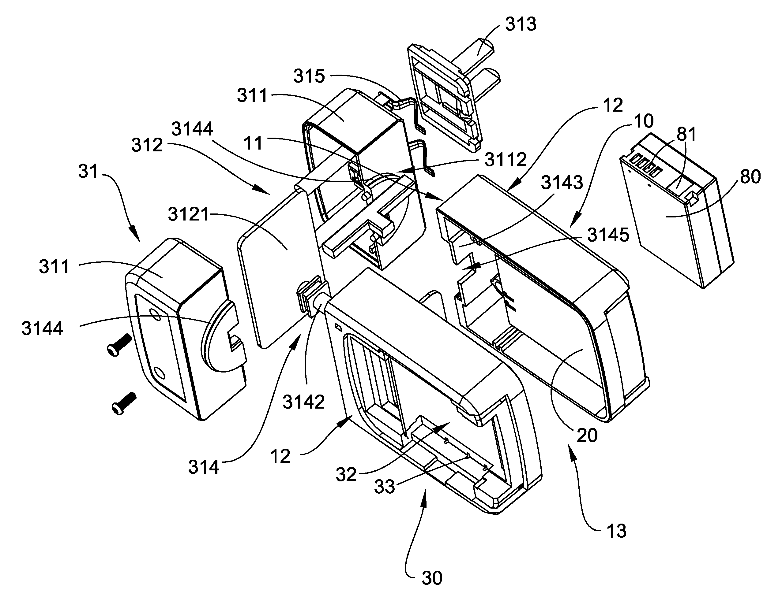
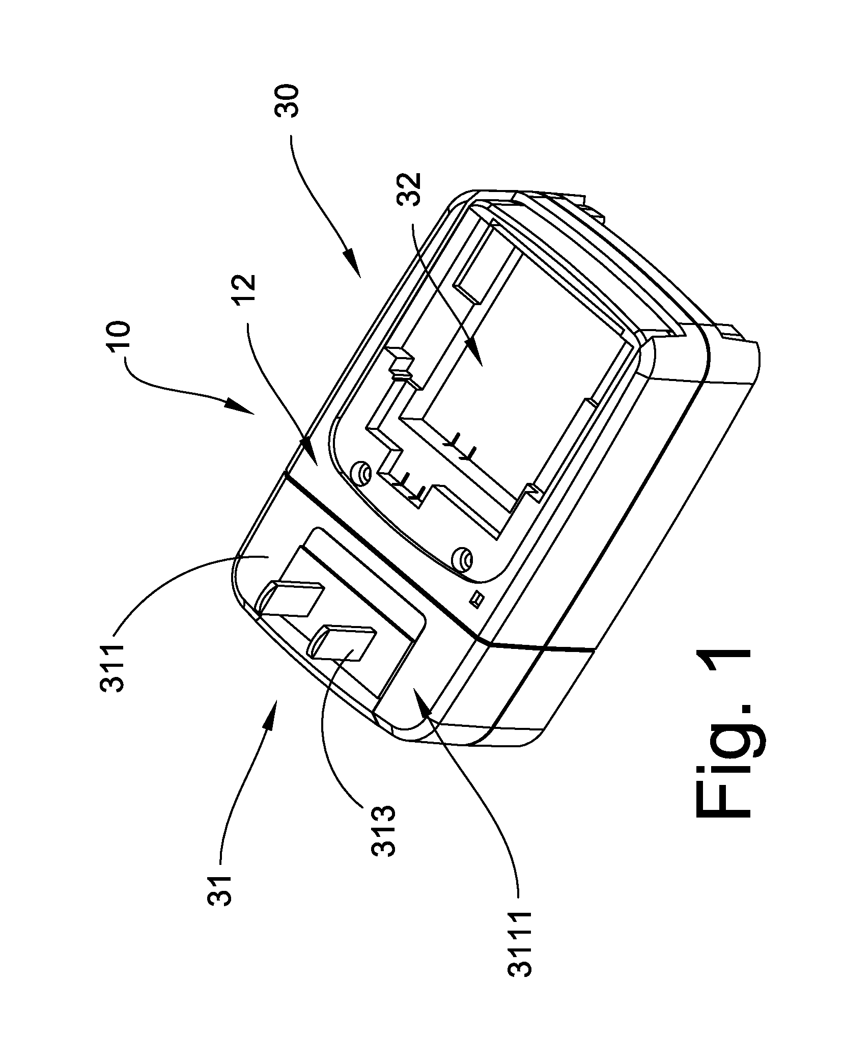
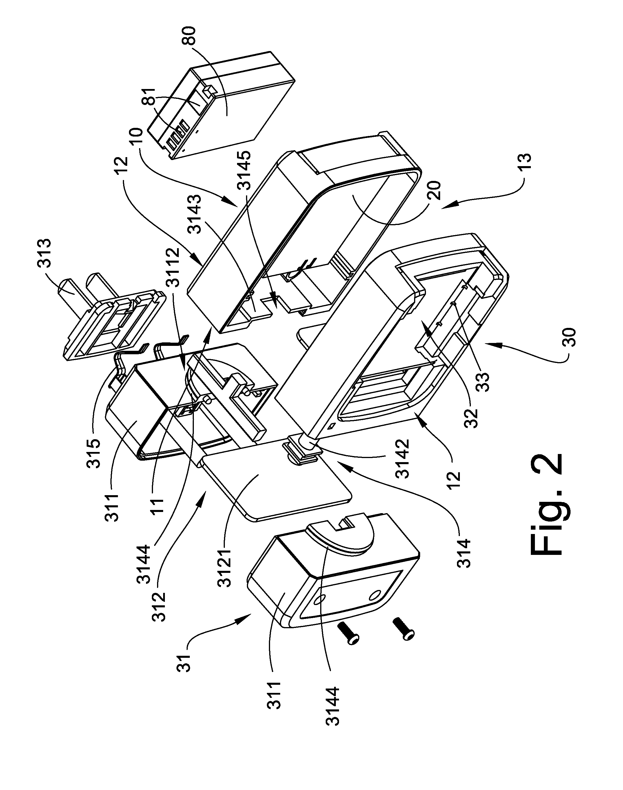
[0029]Referring to FIG. 1 to FIG. 3 of the drawings, a charger for a plurality of rechargeable batteries 80 according to a preferred embodiment of the present invention is illustrated, in which the charger comprises a charger housing 10, a charging circuitry 20, and a multi-sided charging arrangement 30.

[0030]The charger housing 10 defines a connecting side 11, a plurality of charging sides 12 and a receiving cavity 13 formed within the charging sides and the connecting side 11, wherein the charging circuitry 20 is received in receiving cavity 13 of the housing 10.

[0031]The multi-sided charging arrangement 30 comprises a charger connector 31 which is movably mounted to the connecting side 11 of the housing 10, and electrically connects the charging circuitry 20 to an external AC power source, wherein the multi-sided charging arrangement 30 further contains a plurality of charging slots 32 indently formed on the charging sides 12 of the charger housing 10 respectively, wherein each o...


PUM


Abstract

A charger for a plurality of rechargeable batteries includes a charger housing, a charging circuitry and a multi-sided charging arrangement. The charger housing defines a connecting side, and a plurality of charging sides. The charging circuitry is supported by the charger housing. The multi-sided charging arrangement includes a charger connector movably mounted to the connecting side of the housing. The multi-sided charging arrangement also electrically connects the charging circuitry to an external AC power source. The multi-sided charging arrangement further contains a plurality of charging slots indently formed on the charging sides of the charger housing respectively, wherein each of the charging slots is arranged to accommodate one of the rechargeable batteries so that each of the charging sides is arranged to be used for charging the rechargeable batteries by connecting the charger connector to the external AC power source.

Description

BACKGROUND OF THE PRESENT INVENTION[0001]1. Field of Invention[0002]The present invention relates to a charger, and more particularly to a charger comprising a multi-sided charging arrangement, wherein rechargeable batteries can be accommodated on a plurality of charging sides of the charger for being recharged.[0003]2. Description of Related Arts[0004]A conventional charger usually comprises a housing having a charging side, a charging circuitry received in the housing, wherein the charging side has a charging slot indently formed thereon for accommodating at least one rechargeable battery, such as a Ni-MH battery. The rechargeable battery is arranged to be detachably supported in the charging slot for recharging. The charging circuitry is electrically connected to an external power source, such as an external AC power source, wherein the externally acquired electrical power is utilized for charging the rechargeable battery.[0005]A major disadvantage for this type of conventional c...

Claims


Application Information

Patent Timeline
IPC IPC(8): H02J7/02
CPCH02J7/0044H02J7/0027H02J7/0013H02J7/0045
Inventor LAW, HUNG HI
Owner NEW WELL WEALTH CREATION
Learn More