Belt driving apparatus

Active Publication Date: 2013-06-06
DAIHEN CORP
View PDF15 Cites 2 Cited by
  • Summary
  • Abstract
  • Description
  • Claims
  • Application Information

AI Technical Summary

Benefits of technology

The present invention aims to provide a belt driving apparatus that can prevent the belt from deviating during its traveling between two pulleys.

Problems solved by technology

In practice, however, due to errors in making or mounting each pulley, it is difficult to set the rotation axes of the pulleys parallel to each other with sufficient accuracy.
In such a case, the output belt cannot run stably and may break if continues traveling.
When the length of the output belt is increased or the travel speed of the belt is increased to realize high-speed transfer of workplaces, the amount of displacement of the output belt in the width direction increases, which increases the possibility that the above-described problem will occur.

Method used


Image

  • Belt driving apparatus
  • Belt driving apparatus
  • Belt driving apparatus

Examples


Embodiment Construction

[0034]Preferred embodiments of the present invention will be described below with reference to the accompanying drawings.

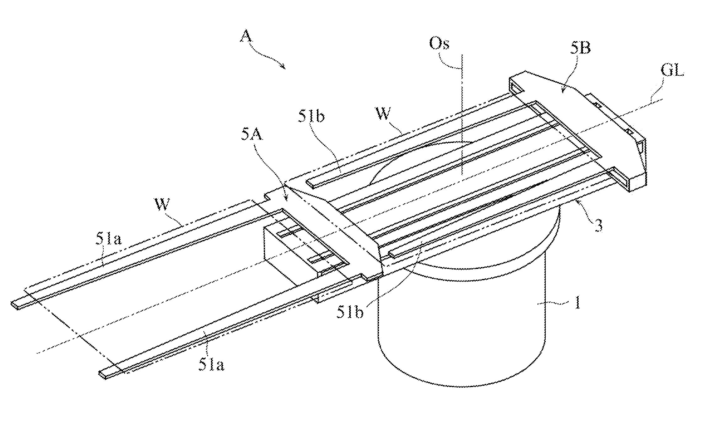
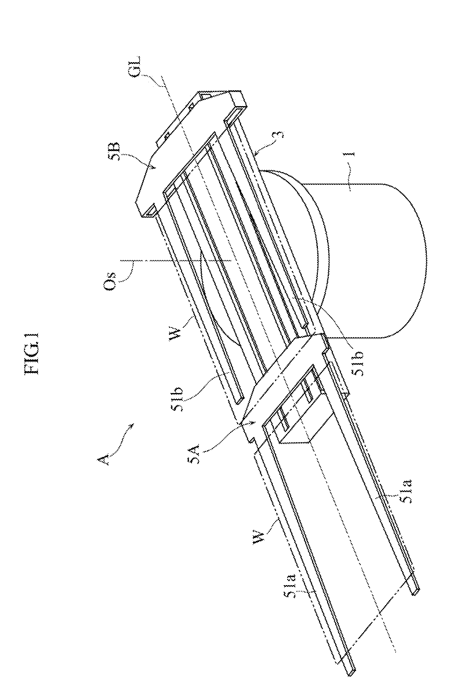
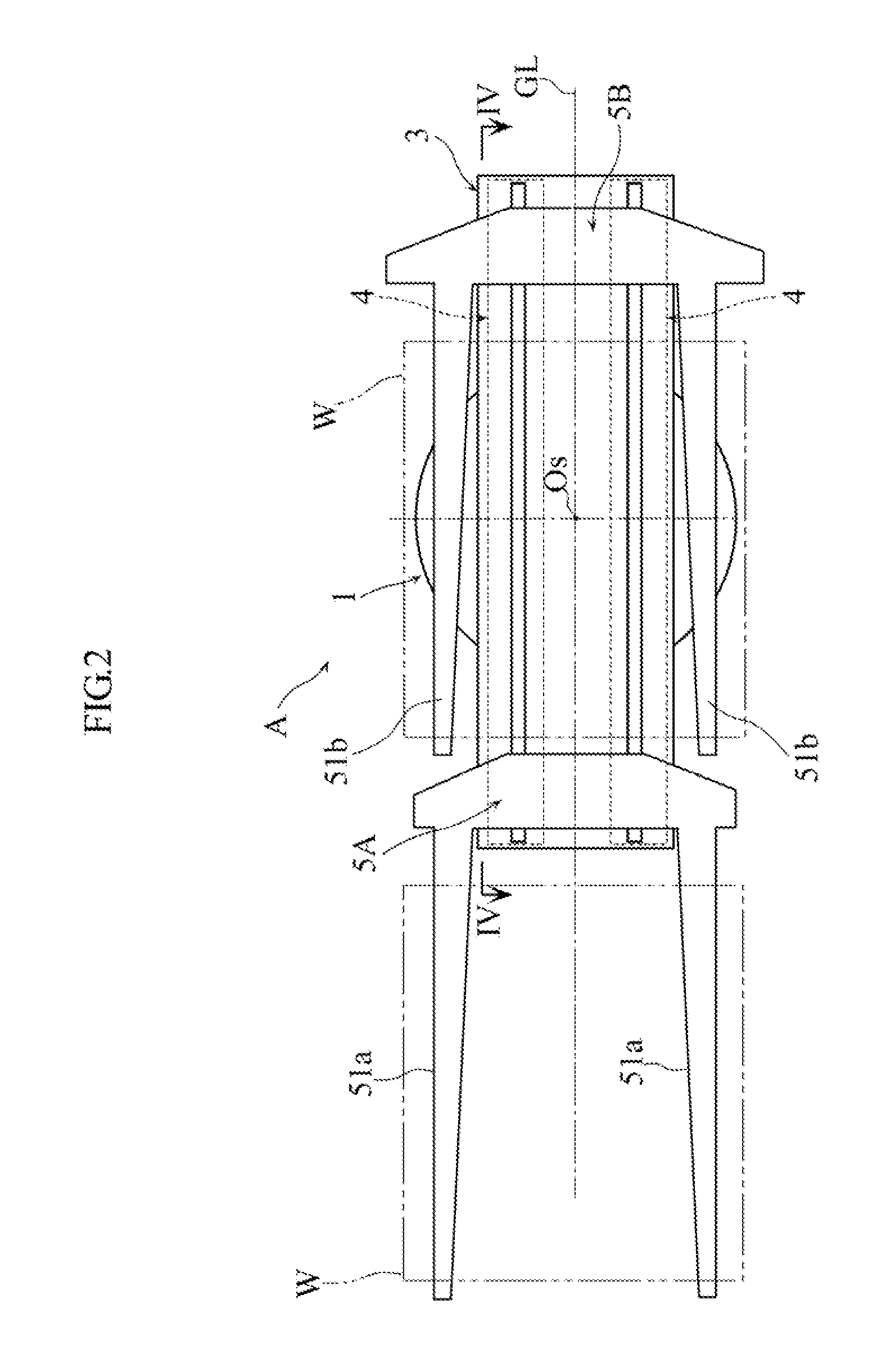
[0035]FIGS. 1-3 show an example of transfer robot including a belt driving apparatus according to the present invention. The transfer robot A is designed to transfer a workpiece W in the form of a thin plate such as a substrate for making a liquid crystal display panel. The transfer robot A includes a stationary base 1, a rotary base 2 supported on the stationary base 1, a guide member 3 supported on the rotary base 2, belt driving apparatuses 4 (see FIG. 2) housed in the guide member 3, and two hands 5A and 5B individually supported by the guide member 3. The hands 5A and 58 are designed to hold the workpiece W in the form of a thin plate in a horizontal posture.

[0036]The rotary base 2 is supported on the stationary base 1 to be movable up and down and refutable about a vertical rotation axis Os. In the stationary bass 1 are provided an elevation motor and a rota...


PUM


Abstract

A belt driving apparatus includes a driving pulley r a driven pulley and an endless toothed belt. Each of the driving pulley and the driven pulley includes an outer circumference surface provided with a plurality of teeth. The toothed belt, wound around the driving pulley and the first driven pulley, includes an inner surface provided with a plurality of teeth arranged to mesh with the teeth of the driving pulley and the first driven pulley. The belt driving apparatus also includes an idler pulley having a belt contact surface coming into contact with the outer surface of the toothed belt. As viewed along the width direction of the belt contact surface, the idler pulley includes a center portion and two end portions sandwiching the center portion. The center portion of the idler pulley is greater in diameter than each of the two end portions.

Description

BACKGROUND OF THE INVENTION[0001]1. Field of the Invention[0002]The present invention relates to a belt driving apparatus including a driving pulley, a driven pulley, and an endless toothed belt wound around the pulleys. In particular, the present invention relates to a belt driving apparatus for use in a transfer robot having a belt-driving-type linear transfer mechanism.[0003]2. Description of the Related Art[0004]As a type of robot for transferring workplaces, robots having a mechanism for moving a hand along a linear movement path (linear movement mechanism) are known (see JP-A-2008-272847, for example). Such a transfer robot having a linear movement mechanism has a simple structure and is inexpensive as compared with articulated robots, and hence, is widely used to transfer a wafer, a glass substrate or the like into or out of a chamber in manufacturing a semiconductor device or a liquid crystal panel, for example.[0005]The transfer robot disclosed in JP-A-2008-272847 includes...

Claims


Application Information

Patent Timeline
IPC IPC(8): F16H7/02
CPCF16H7/023F16H19/06F16H2019/0686B65H2404/25F16C13/006F16G1/28F16H2007/0865
Inventor TAKARABE, SAYAKO
Owner DAIHEN CORP
Why Eureka
Try Eureka