
Disposable circumcision anastomat

Active Publication Date: 2013-06-06
SHANG JIANZHONG +1
View PDF9 Cites 10 Cited by
  • Summary
  • Abstract
  • Description
  • Claims
  • Application Information

AI Technical Summary

Benefits of technology

The patent describes a disposable circumcision apparatus that includes a circular ring and a blade which hold a gasket made of non-woven fabrics or absorbent material to retain an anesthetic drug. The apparatus is comfortable, reliable and safer due to its pain-relieving property. The patients have options to choose different types of disposable circumcision apparatus. The hinged structure makes the apparatus more convenient to operate.

Problems solved by technology

The present technology, however, may cause discomfort to patients, as they are required to wear the device shown in FIGS. 1-4 for several days after circumcision surgery.
Typically, patients feel pain due to the incision on the prepuce.
Additionally, the incision may become easily infected when from wearing the present technology after surgery.

Method used


Image

  • Disposable circumcision anastomat
  • Disposable circumcision anastomat
  • Disposable circumcision anastomat

Examples


first embodiment

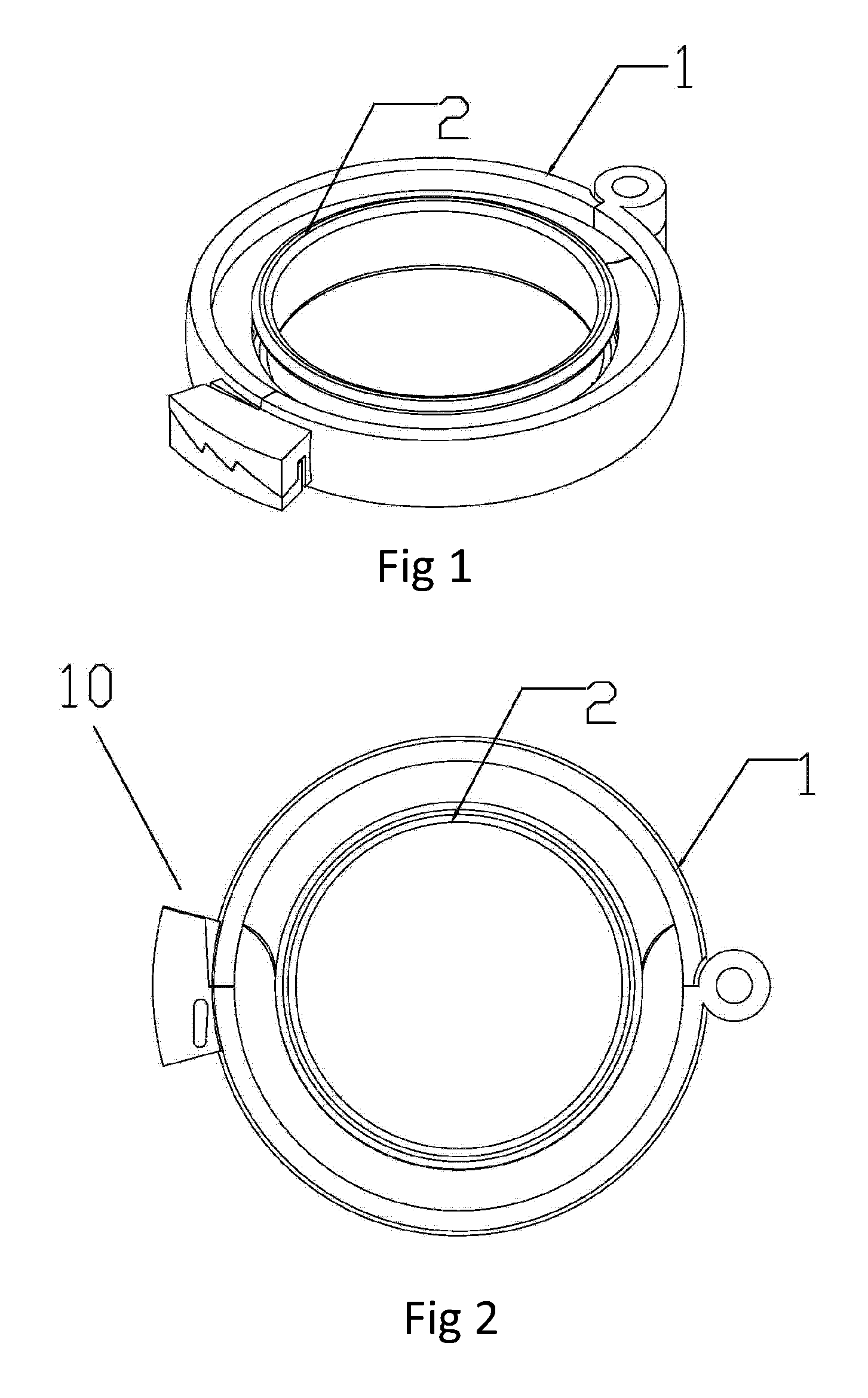
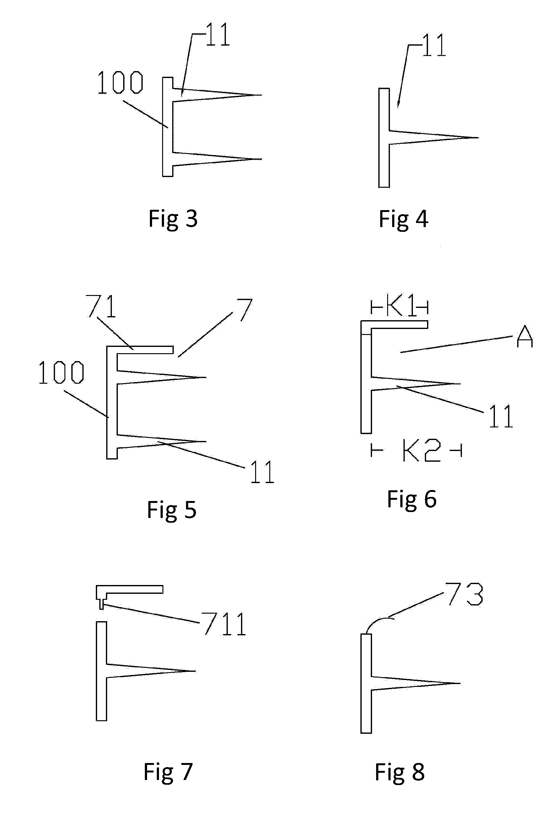
[0039]FIG. 5 illustrates the cross-section of the external ring 1 of a disposable circumcision anastomat. The annular blade 11, in this embodiment, comprises a dual-blade structure. The retainer 7 comprises an annular sheet 71 in the shape of a common, mechanical washer, extending inwardly from the sidewall 100 of external ring 1. The annular sheet 71 comprises an opening 710 which corresponds with the opening 10 of the external ring 1. In this embodiment, the width K1 of the annular sheet 71 is less than the width K2 of the annular blade 11. The annular sheet 71 and the upper blade of annular blade 11 form an annular retaining space A for securing a gasket. The multi-blade can also use this retainer and retaining space.

second embodiment

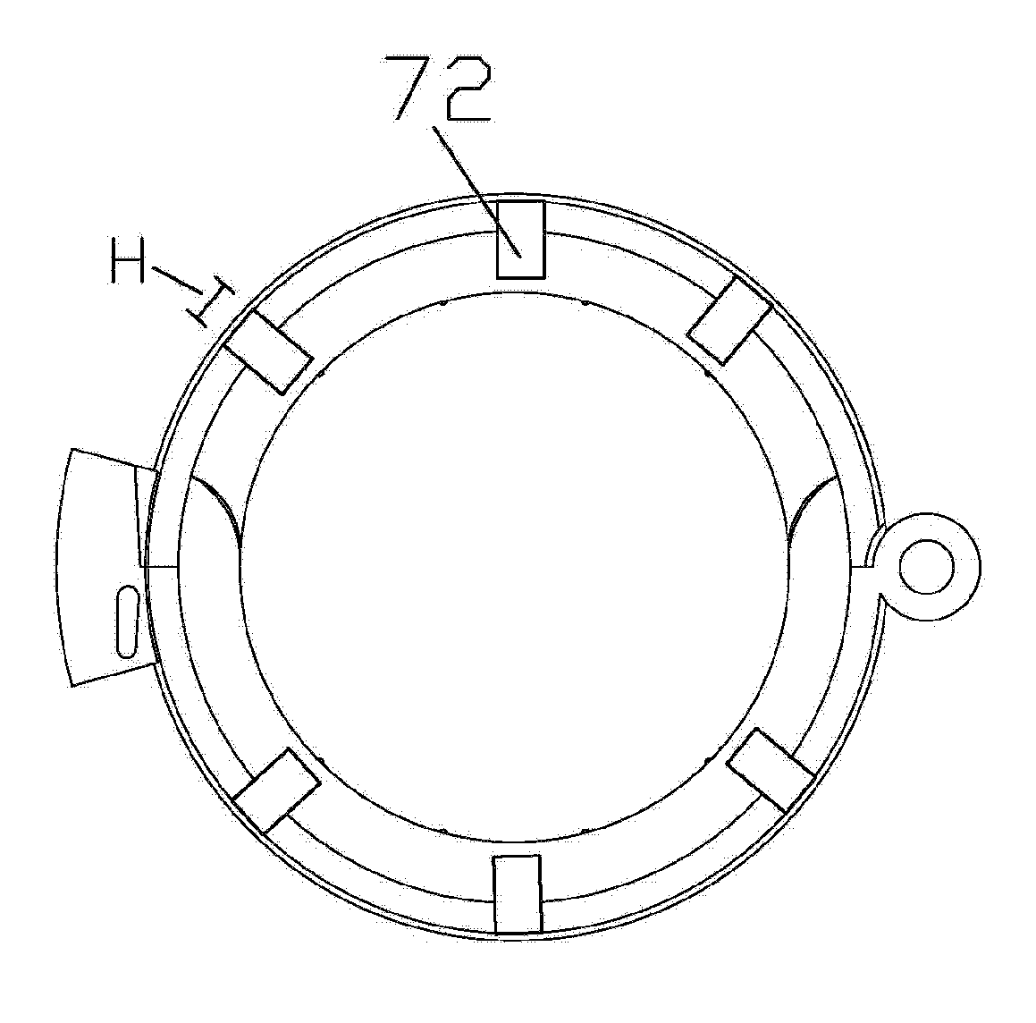
[0040]FIG. 11 illustrates the external ring 2 of a The retainer 7 comprises tabs 72 extending inwardly from the sidewall of the external ring 1. In this embodiment, the length K3 of tab 72 is less than a width K2 of the annular blade 11. The tabs 72 and the upper blade of annular blade 11 form annular retaining space for retaining a gasket. In other embodiment, the number of tabs 72 may be greater or less than the number of tabs shown in FIG. 11. Furthermore, the width H of each tab can be greater or less than whit is shown in FIG. 11.

third embodiment

[0041]FIG. 8 illustrates a cross-section of external ring 1 of a The retainer 7 comprises a series of hooks 73 extended inwardly from the sidewall of external ring 1. The hooks 73 and upper blade of annular blade 11 form an annular retaining space for retaining a gasket. The hooks 73 may comprise shapes other than that shown in FIG. 8 and a greater or fewer number of hooks 73 may be used in other embodiments. The hooks 73 shown in the figure can also comprise any other structure that is able to retain a gasket against the upper blade of annular blade 11.

[0042]FIGS. 5, 6, and 7 illustrate a cross-section of external ring 1 and three embodiments of retainer, in those embodiments the retainer is the annular sheet 71. In FIG. 5, the the annular sheet 71 is formed as a unified structure with the annular blade 11. In FIG. 6, retainer 7 comprises an independent, removable structure. FIG. 7 shows the retainer 7 of FIG. 6 in an exploded view, comprising a male connection portion 711 for ins...


PUM


Abstract

A disposable circumcision anastomat comprises an internal ring (2) and an external ring (1) having an opening (10). The internal ring (2) substantially matches an external ring (1). The external ring (1) includes a sidewall (100). The sidewall (100) is provided with a retainer (7) for holding a gasket. The retainer (7) is an annular ring (71) extended inwardly from the sidewall (100) of the external ring. The annular ring (71) is equipped with an opening (710), corresponding to opening (10) on the external ring. The width (K1) of the annular ring is less than the width (K2) of the blade. The anastomat is safe, reliable, and able to reduce pain experienced by patients after surgery.

Description

CROSS REFERENCE TO RELATED APPLICATIONS[0001]This application is the national stage of PCT application serial number PCT / CN2011 / 001385, filed on Aug. 19, 2011, which claims priority to Chinese application serial number 201020297600.6, filed on Aug. 19, 2010, the entire contents of which are incorporated herein.BACKGROUND[0002]1. Field of the Invention[0003]The invention relates to a type of medical apparatus, especially a type of disposable circumcision anastomat.[0004]2. Related Art[0005]Redundant prepuce or phimosis is one of the reasons for male urinary system infection and aggravation of sexually transmitted diseases. Redundant prepuce or phimosis can cause urinary tract infection that may lead to chronic prostatitis, which presents as a series of symptoms such as back pain, impotence and prospermia. In addition, the effect of male circumcision has been widely recognized in reducing the transmission HIV. Therefore, removing redundant foreskin or phimosis is a good way to prevent...

Claims


Application Information

Patent Timeline
IPC IPC(8): A61B17/326
CPCA61B2017/0023A61B17/326
Inventor SHANG, JIANZHONGSHANG, JINGJING
Owner SHANG JIANZHONG
Learn More