Heat sink fin structure blocking electromagnetic radiation

a technology of electromagnetic radiation and heat sink, which is applied in the direction of electrical apparatus construction details, electrical apparatus casings/cabinets/drawers, instruments, etc., can solve the problem of electromagnetic radiation interference with the efficient operation of electronic components

Inactive Publication Date: 2013-06-13
LENOVO ENTERPRISE SOLUTIONS SINGAPORE
View PDF12 Cites 14 Cited by
  • Summary
  • Abstract
  • Description
  • Claims
  • Application Information

AI Technical Summary

Problems solved by technology

Left unabated, EMR interferes with the efficient operation of electronic components.
However, small vents generally impede the flow of air through the chass

Method used


Image

  • Heat sink fin structure blocking electromagnetic radiation
  • Heat sink fin structure blocking electromagnetic radiation
  • Heat sink fin structure blocking electromagnetic radiation

Examples


Embodiment Construction

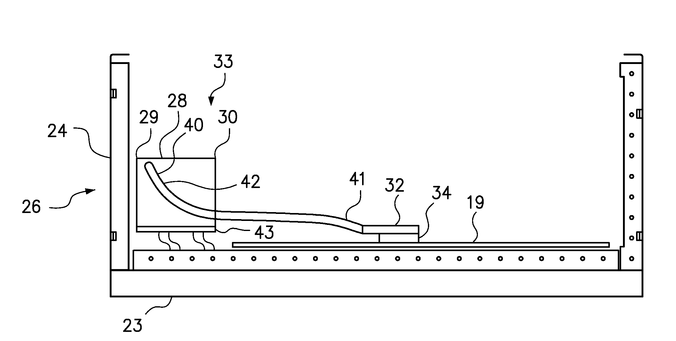
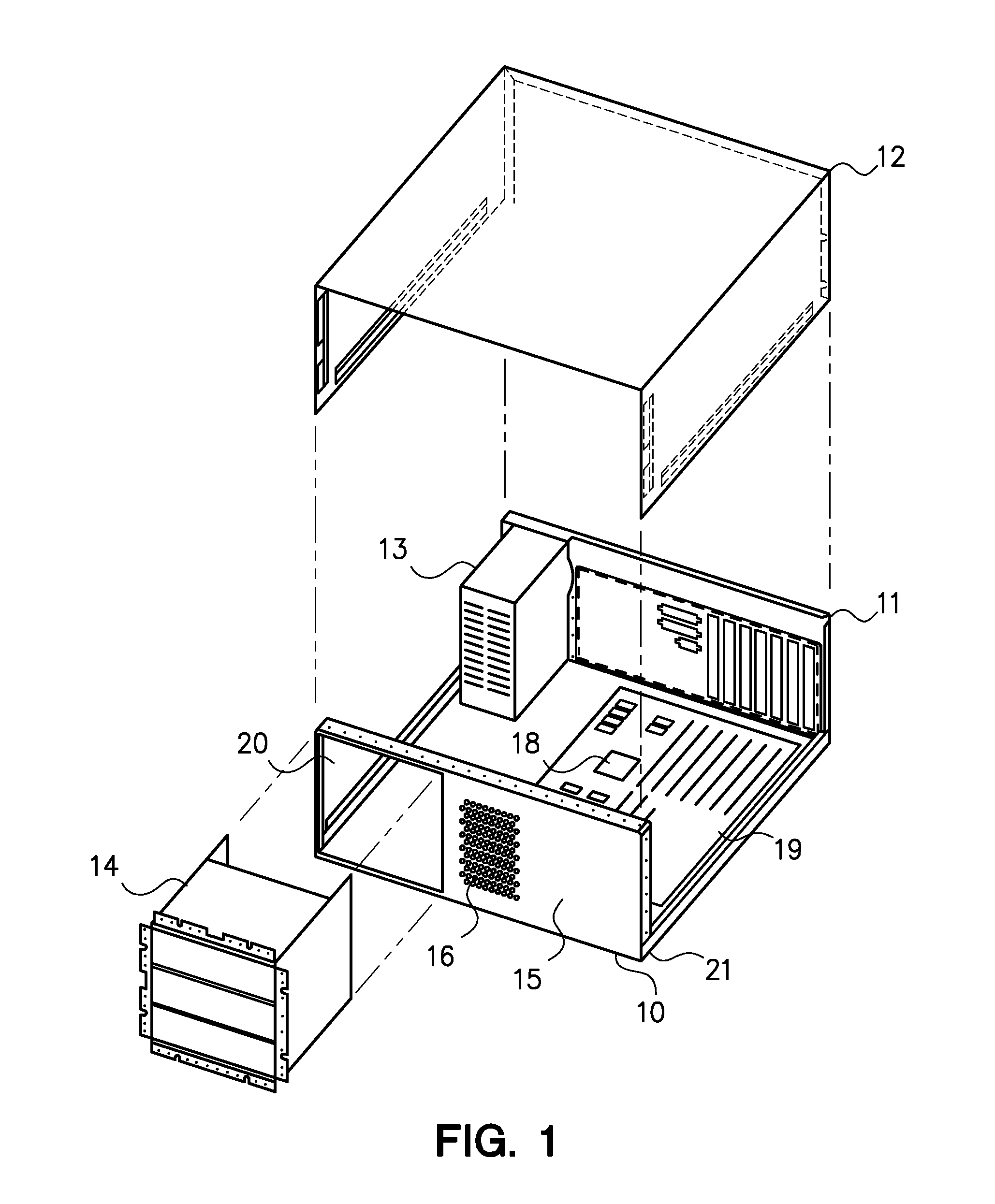
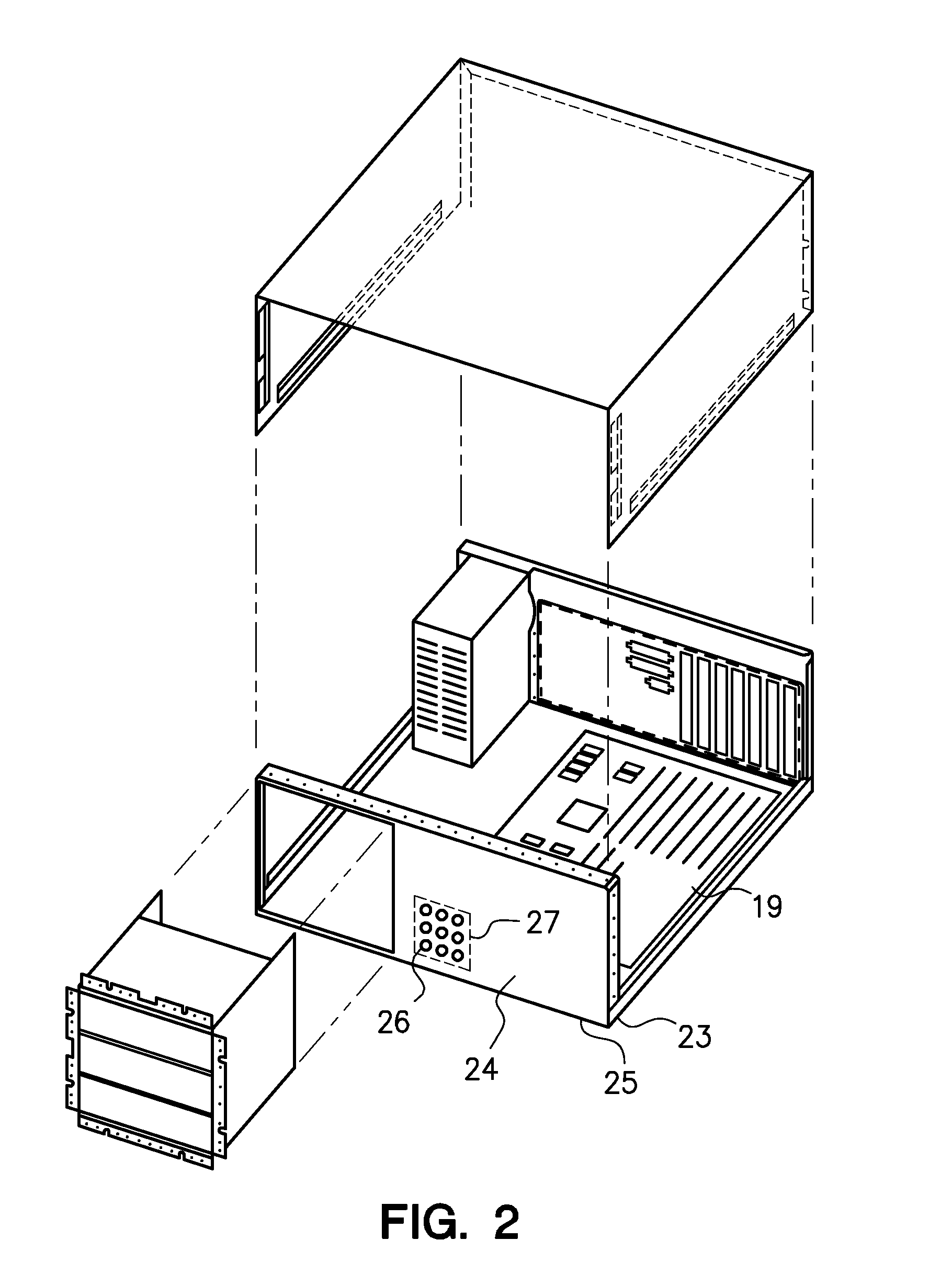
[0015]One embodiment of the present invention provides an electromagnetic radiation (EMR) containment system comprising a heat sink to cool a heat-generating electronic component within a computer chassis, where the heat sink has a fin structure that cooperates with low-impedance vents within a bezel to provide improved cooling air flow to the heat sink and to block EMR from traversing the chassis. The fin structure comprises an inlet face, an outlet face and a plurality of interconnected air channels therebetween. The inlet face of the fin structure is disposed at a forward position near an air inlet across front of the chassis, and the bezel with low-impedance vents is connected to the front of the chassis to position the vents across the air inlet proximal to the inlet face of the fin structure. The fin structure is thermally coupled to a base in thermal contact or communication with a heat-generating electronic component. The fin structure dissipates heat from the component to a...


PUM

PropertyMeasurementUnit
Lengthaaaaaaaaaa
Lengthaaaaaaaaaa
Lengthaaaaaaaaaa

Abstract

A system to remove heat from a heat-generating electronic component within a computer chassis and to contain electromagnetic radiation from traversing high-throughput vents in a bezel that forms a portion of the chassis containment structure comprises a heat sink having a fin structure with an inlet face, an outlet face and interconnected air channels therethrough, a base to engage the component and to transfer heat from the component to the fin structure, wherein the inlet face of the fin structure is disposed proximate the vents to block electromagnetic radiation from traversing the vents. In one embodiment, a heat pipe or a spreader bar moves heat from a base engaging a component distal from the bezel to the fin structure having an air inlet face proximal to the vents.

Description

BACKGROUND[0001]1. Field of the Invention[0002]The present invention relates to heat sinks to cool heat-generating electronic components within a computer chassis.[0003]2. Background of the Related Art[0004]Computer systems often rely on heat sinks positioned on heat-generating electronic components, such as processors, to maintain performance of the component by removing heat and maintaining a favorable operating temperature. Heat sinks generally conduct heat generated by the component to fins where the heat is transferred to air flowing across the large surface area of the fins. Heat sinks are available with several types of air-cooled fins including pin fins, straight fins, folded fins, flared fins and extruded fins. With increasing processor power densities, more heat is generated by processors disposed within the limited space of a computer chassis, thereby giving rise to a need for improved heat sink systems.[0005]Most computer chassis, especially those in high density compute...

Claims


Application Information

Patent Timeline
IPC IPC(8): G06F1/20H01P1/22H05K7/20
CPCG06F1/20H01L23/427H01L23/467H05K9/0041Y10T29/49018H01L2924/0002G06F1/182H01L2924/00
Inventor BUSCH, DIANE S.GLOVER, TROY W.JUNE, MICHAEL S.RAMINENI, PRADEEP
Owner LENOVO ENTERPRISE SOLUTIONS SINGAPORE
Why Eureka
Try Eureka