
Perimeter monitoring device for work vehicle

Active Publication Date: 2013-06-13
KOMATSU LTD
View PDF4 Cites 52 Cited by
  • Summary
  • Abstract
  • Description
  • Claims
  • Application Information

AI Technical Summary

Benefits of technology

The present invention aims to enable an operator to easily identify the most important obstacle when multiple obstacles are detected in the surrounding of a work vehicle. The device uses cameras to capture images of the obstacles and displays a single camera image ranked in priority based on the vehicle's traveling state. The image is accompanied by a bird's-eye view that highlights the position of the obstacle, making it easier to quickly check its location. The device also emits different types of alert sounds based on the obstacle's position and the operator's risk level, allowing them to quickly understand the magnitude of the risk. Overall, the invention simplifies the process of identifying and prioritizing obstacles, improving operational efficiency and safety.

Problems solved by technology

Therefore, it is difficult for operators thereof to grasp surrounding statuses by means of side mirrors and etc.
However, the number of obstacles in the surrounding of a vehicle is not limited to one, and a plurality of obstacles may exist in some cases.
JP-A-2010-198519 to a work vehicle such as a dump truck, even an object, which is not required to be recognized as an obstacle, is supposed to be displayed on a monitor and this makes it difficult to gasp an obstacle that should be normally most watched out.
It is quite difficult for an operator of such work vehicle to gasp the status of the opposite side to the side on which the operating room is disposed.

Method used


Image

  • Perimeter monitoring device for work vehicle
  • Perimeter monitoring device for work vehicle
  • Perimeter monitoring device for work vehicle

Examples


Embodiment Construction

[0030]An exemplary embodiment of the present invention will be hereinafter explained with reference to drawings. It should be noted that in the following explanation, “front”, “rear”, “left” and “right” are terms set based on an operator seated on an operator seat and “a vehicle width direction” is a synonym for “a right-and-left direction”.

Overall Structure of Dump Truck

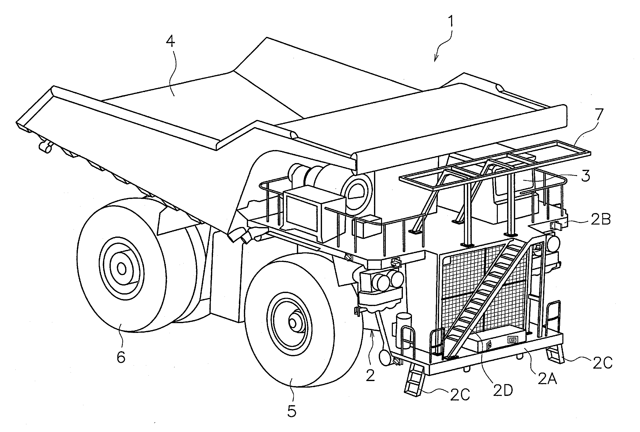
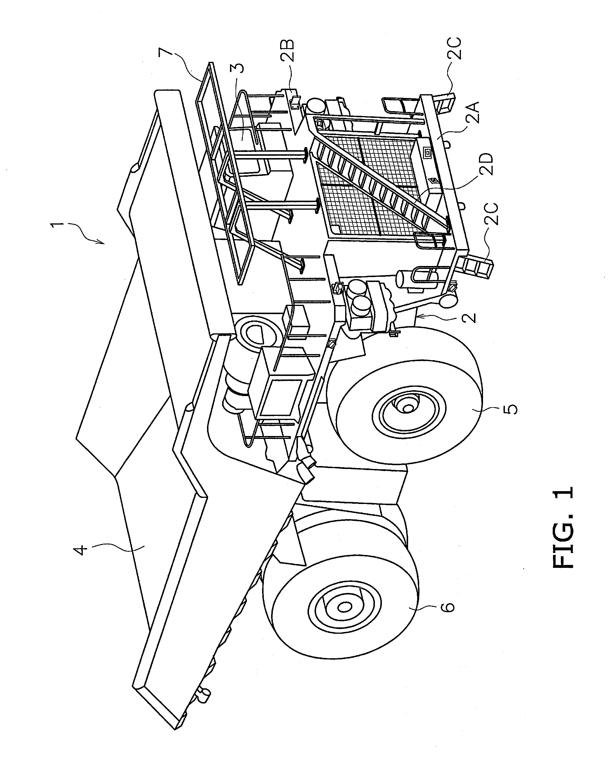
[0031]FIG. 1 is a perspective view illustrating an entire structure of a dump truck 1 including a perimeter monitoring device according to an exemplary embodiment of the present invention. The dump truck 1 is a self-propelled supersized work vehicle to be used for mining works and etc.

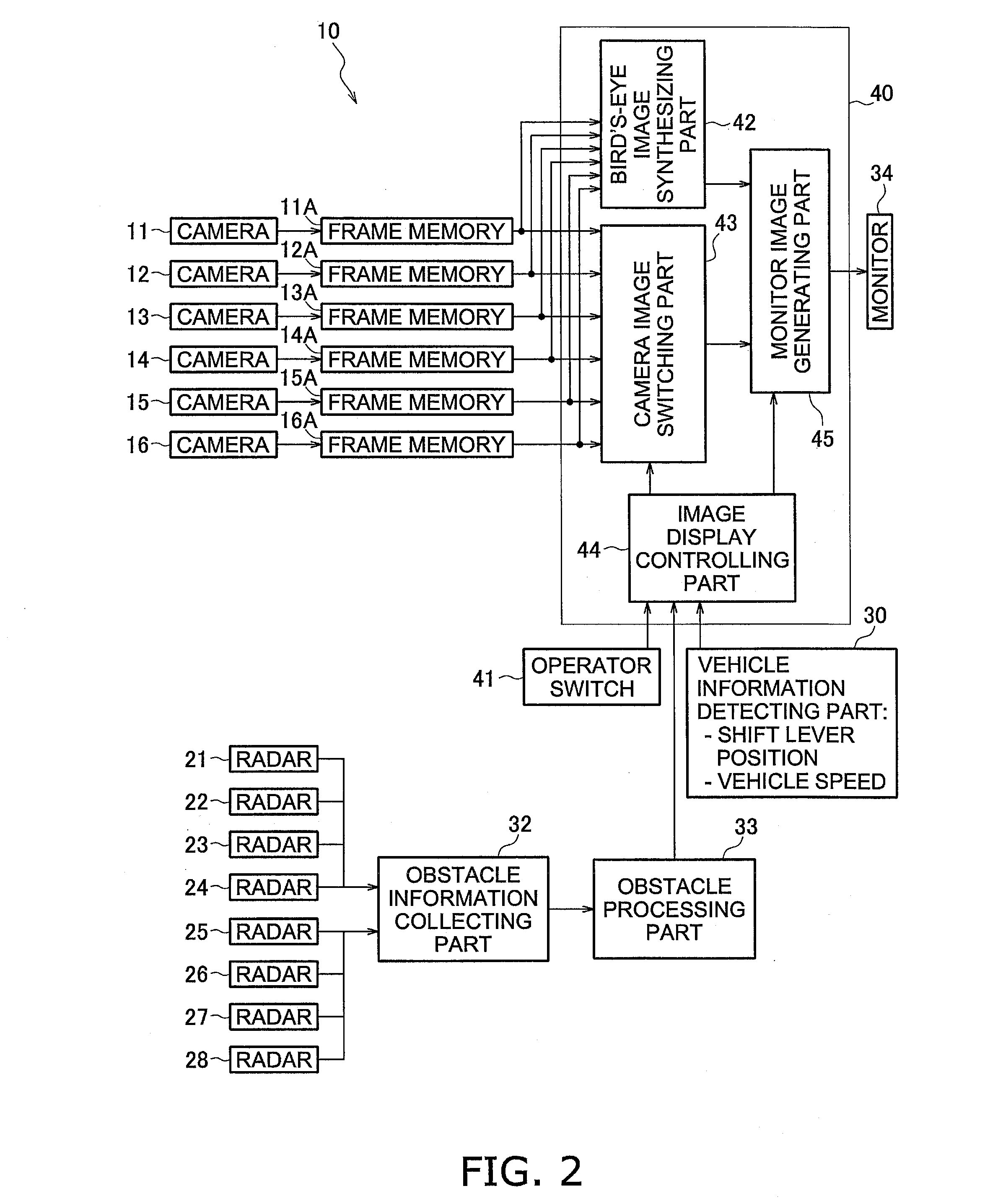
[0032]The dump truck 1 mainly includes a vehicle body frame 2, a cab 3 as an operating room, a vessel 4, two front wheels 5, two rear wheels 6 and a base 7 for installing thereon a pantograph for power supply. Further, the present dump truck 1 includes a perimeter monitoring device 10 (see FIG. 2) configured to monitor the surrounding ...


PUM


Abstract

A perimeter monitoring device for a work vehicle is configured to monitor a surrounding of the work vehicle and display a monitored result on a display device. The perimeter monitoring device includes cameras, a bird's-eye image display unit, obstacle detecting sensors, a camera image specifying unit, and a camera image displaying unit. The camera image specifying unit is configured to specify one or more camera images in which one or more of obstacles are captured when the one or more of obstacles are detected by the obstacle detecting sensors. The camera image displaying unit is configured to display a relevant camera image in alignment with the bird's-eye image on the display device when a plurality of camera images are specified by the camera image specifying unit, the relevant camera image being ranked in a high priority ranking based on a priority order set in accordance with travelling states.

Description

CROSS-REFERENCE TO RELATED APPLICATIONS[0001]This application claims priority to Japanese Patent Application No. 2011-127476 filed on Jun. 7, 2011, and Japanese Patent Application No. 2011-129461 filed on Jun. 9, 2011, the disclosures of which are hereby incorporated herein by reference in their entireties.TECHNICAL FIELD[0002]The present invention relates to a perimeter monitoring device, and particularly to a perimeter monitoring device configured to monitor the surrounding of a work vehicle and display a monitored result on a display device.BACKGROUND ART[0003]Dump trucks, used for carrying crushed stones in mines or etc., have been provided as supersized work vehicles. Compared to vehicles such as normal trucks, dump trucks of this type have a remarkably large vehicle width and a large longitudinal length. Therefore, it is difficult for operators thereof to grasp surrounding statuses by means of side mirrors and etc. In view of this, as described in U.S. Patent Application Publi...

Claims


Application Information

Patent Timeline
IPC IPC(8): H04N7/18
CPCB60R1/00B60R2300/105B60R2300/301B60R2300/303B60R2300/607G08G1/166H04N7/18E02F9/261H04N7/181B60P1/283B60R2300/8093H04N23/63B60K35/29B60K2360/186B60R1/27B60R1/28H04N23/90B60K35/00B60P1/04B60Q9/008B60R2300/802
Inventor MITSUTA, SHINJIHARADA, SHIGERUTANUKI, TOMIKAZUMASUTANI, EISHINNAKANISHI, YUKIHIROKURIHARA, TAKESHITSUBONE, DAIMACHIDA, MASAOMI
Owner KOMATSU LTD
Learn More