Conversion of measured data between measurement modalities

Pending Publication Date: 2021-12-30
ROBERT BOSCH GMBH
View PDF0 Cites 0 Cited by
  • Summary
  • Abstract
  • Description
  • Claims
  • Application Information

AI Technical Summary

Benefits of technology

[0033]An advantage of the test method provided herein is that the control logic may be checked in isolation. In a test during driving operation, in which sensors of the vehicle detect the natural setting, the proposed response is ultimately a function of both the detection and processing of the setting by the sensor as well as of the further processing by the control logic. If the proposed response does not correspond to the

Problems solved by technology

If the proposed response does not correspond to the setpoint response, a poor quality of the raw signal detected by the sensor and a sub-optimal processing in the sensor, in addition to a sub-optimal processing in the control logic, are c

Method used


Image

  • Conversion of measured data between measurement modalities
  • Conversion of measured data between measurement modalities
  • Conversion of measured data between measurement modalities

Examples


Example

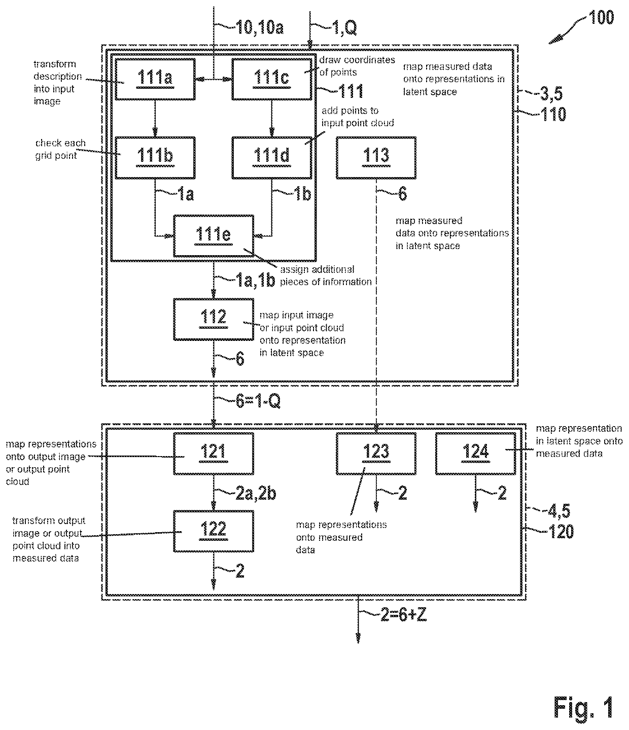
[0053]FIG. 1 is a schematic flowchart of one exemplary embodiment of method 100 for converting measured data 1 of a source measurement modality Q into realistic measured data of a target measurement modality Z.

[0054]Measured data 1 are marked with the specifics of source measurement modality Q. These measured data 1 are mapped in step 110 using encoder 3 of a trained encoder-decoder arrangement 5 onto representations 6 in a latent space. These representations 6 are compressed as compared to the original measured data 1 and simultaneously purged of the specifics of the source measurement modality Q.

[0055]In step 120, representations 6 are mapped onto realistic measured data 2 of target measurement modality Z using decoder 4 of encoder-decoder arrangement 5. Measured data 2 are thus quasi “decompressed” from representations 6, and the specifics of target measurement modality Z are added.

[0056]According to block 111, measured data 1 of source measurement modality Q may be transformed i...


PUM


Abstract

A method for converting measured data of at least one source measurement modality into realistic measured data of at least one target measurement modality. The method includes: the measured data of the source measurement modality are mapped onto representations in a latent space using an encoder of a trained encoder-decoder arrangement, and the representations are mapped onto the realistic measured data of the target measurement modality using the decoder of the encoder-decoder arrangement, the amount of information of the representations of measured data in the latent space being smaller than the amount of information of the measured data.

Description

CROSS REFERENCE[0001]The present application claims the benefit under 35 U.S.C. § 119 of German Patent Application No. DE 102020207887.4 filed on Jun. 25, 2020, which is expressly incorporated herein by reference in its entirety.[0002]The present invention relates to the conversion of measured data of a source measurement modality into measured data of a target measurement modality, with which, for example, a control logic for a driving assistance system or a system for the at least semi-automated driving of a vehicle may be checked.BACKGROUND INFORMATION[0003]Driving assistance systems and systems for the at least semi-automated driving of a vehicle make decisions about driving maneuvers on the basis of sensory observations of the vehicle surroundings. The observations are recorded, for example, in the form of camera images, video images, heat images, ultrasonic images, radar data and LIDAR data. These raw signals are further processed in various levels of abstraction and also redu...

Claims


Application Information

Patent Timeline
IPC IPC(8): G01S13/90G01S17/89
CPCG01S13/90G01S17/89G01D21/00G01S7/2955G01S13/931G06F11/3664G06F11/3696G06F11/3688G06V20/56G06V10/82G06N3/08G06N3/045G05D1/0257B60W40/02B60W60/001G06N20/00G01S13/89G06F18/00
Inventor JUNGINGER, ANDREJ
Owner ROBERT BOSCH GMBH
Why Eureka
Try Eureka