
Aluminum tube milling process

An aluminum tube and milling technology, applied in the field of mechanical milling, can solve the problems of adding cleaning steps, products that are easy to contaminate, and a low degree of automation, so as to reduce processing costs, improve timeliness, and avoid multiple clamping effects.

Inactive Publication Date: 2019-07-19
江苏富浩电子科技有限公司
View PDF7 Cites 2 Cited by
  • Summary
  • Abstract
  • Description
  • Claims
  • Application Information

AI Technical Summary

Problems solved by technology

[0002] Milling is a mechanical milling method in which a milling cutter is used as a tool to mill the surface of an object. In the prior art, the degree of automation of aluminum tube milling is not high, and most of them adopt traditional NC milling operations. Different product shapes require supporting fixtures to realize the milling process. Aluminum tube milling includes various processes such as picking, positioning, deburring and milling. Each process needs to be completed by a separate program, which often requires manual labor to operate the machine, which greatly improves the difficulty of clamping and replacing the carrier. The milling process consumes a lot of manpower and material resources, and the efficiency is low, which is very inconvenient
[0003] Generally, machining centers use cutting fluid water cooling to cool down the cutting tool, which is easy to contaminate the product, and subsequent cleaning steps need to be added, which increases time and increases production costs. Based on the above defects and deficiencies, it is necessary to improve the existing technology

Method used


Image

  • Aluminum tube milling process
  • Aluminum tube milling process
  • Aluminum tube milling process

Examples


Embodiment Construction

[0030] The preferred embodiments of the present invention will be described in detail below in conjunction with the accompanying drawings, so that the advantages and features of the invention can be more easily understood by those skilled in the art, so as to define the protection scope of the present invention more clearly.

[0031] see Figure 1 to Figure 5 , the embodiment of the present invention includes:

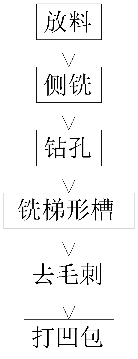
[0032] An aluminum tube milling process, the aluminum tube milling process comprises the following steps:

[0033] Step 1: Unloading: manual unloading, the mechanical arm automatically picks and places the aluminum tube blank on the fixture, the fixture is pressed against the product by external force, and the fixture is opened. When the product is processed, the fixture is held tightly to prevent the product from moving due to force during milling , so that it can process numerical variables. The product fixture adopts the method of indexing plate transportation, and...


PUM


Abstract

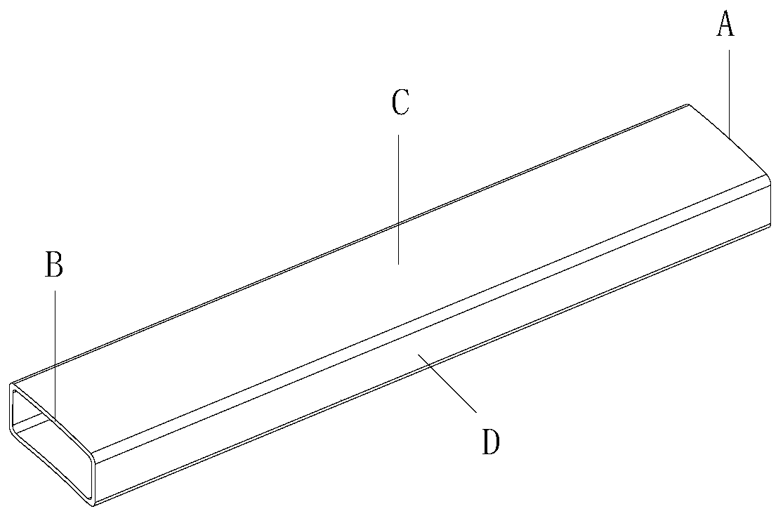
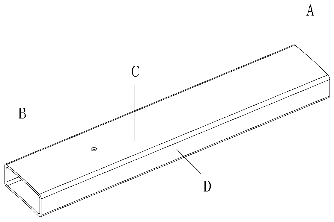
The invention discloses an aluminum tube milling process. The aluminum tube milling process comprises the following steps that material placement is carried out, wherein a mechanical arm automaticallytakes and places an aluminum tube blank on a fixture, and the product fixture adopts the manner of indexing tray transportation; side milling is carried out, wherein a milling cutter is moved downwards to mill the two end faces A and B of the aluminum tube blank, and rough milling and finishing milling are carried out; drilling is carried out, wherein a drilling knife is moved downwards to drilla hole in the upper end surface C of an aluminum tube; dovetail groove milling is carried out, wherein a servo control electric spindle is used for driving the milling cutter to mill a trapezoidal groove in the end face B of the aluminum tube, and rough milling and finishing milling are carried out; deburring is carried out, wherein a diamond brush is used for deburring the end faces of the aluminum tube and the trapezoidal grooves; and concave bag punching is carried out, wherein the mechanical arm grips a product into a concave bag punching die, concave bag processing is carried out on the two side faces D of the aluminum tube. In the above steps, waste chippings are sucked away in dust extraction method, and the cutters are cooled by blowing the cold air. In the above manner, the present technology replaces conventional CNC machining operation, and multiple clamping, carrier replacing and debugging are avoided.

Description

technical field [0001] The invention relates to the technical field of mechanical milling, in particular to an aluminum tube milling process. Background technique [0002] Milling is a mechanical milling method in which a milling cutter is used as a tool to mill the surface of an object. In the prior art, the degree of automation of aluminum tube milling is not high, and most of them adopt traditional NC milling operations. Different product shapes require supporting fixtures to realize the milling process. Aluminum tube milling includes various processes such as picking, positioning, deburring and milling. Each process needs to be completed by a separate program, which often requires manual labor to operate the machine, which greatly improves the difficulty of clamping and replacing the carrier. The milling process consumes a lot of manpower and material resources, and the efficiency is low, which is very inconvenient. [0003] Generally, machining centers use cutting flui...

Claims


Application Information

Patent Timeline
IPC IPC(8): B23P15/00
CPCB23P15/00
Inventor 许春锋王晓东邓建肖
Owner 江苏富浩电子科技有限公司
Learn More