
Automatic high-pressure washing and deburring equipment for automobile parts

A technology for auto parts and high-pressure flushing, which is applied in metal processing equipment, grinding machine parts, grinding/polishing equipment, etc., can solve the problem of low grinding efficiency, improve grinding efficiency, improve efficiency, and avoid multiple times clamping effect

Active Publication Date: 2022-03-18
润斯普瑞超声科技(苏州)有限公司
View PDF5 Cites 0 Cited by
  • Summary
  • Abstract
  • Description
  • Claims
  • Application Information

AI Technical Summary

Problems solved by technology

[0004] The purpose of the present invention is to solve the disadvantages of low grinding efficiency and the need for separate flushing in the prior art, and propose an automatic high-pressure flushing and deburring equipment for auto parts

Method used


Image

  • Automatic high-pressure washing and deburring equipment for automobile parts
  • Automatic high-pressure washing and deburring equipment for automobile parts
  • Automatic high-pressure washing and deburring equipment for automobile parts

Examples


Embodiment 1

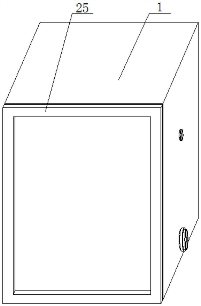
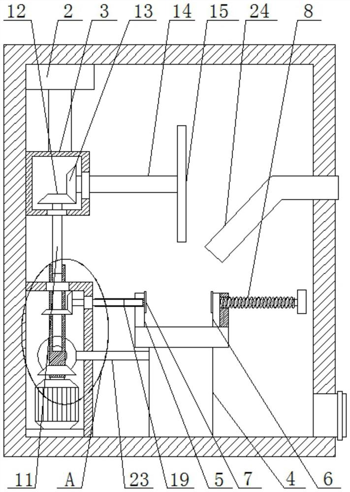
[0026] refer to Figure 1-4 , an automatic high-pressure flushing and deburring equipment for auto parts, comprising a housing 1, a cylinder 2 is arranged in the housing 1, a limit box 3 is fixedly installed on the telescopic rod of the cylinder 2, a base 4 is slidably installed in the housing 1, A fixed plate 5 is fixedly installed on the base 4, a splint 6 is slidably installed on the base 4, a circular plate 7 is rotatably installed on the fixed plate 5 and the splint 6, and a screw 8 is threaded on the base 4, and the screw 8 is connected to the splint 6 in rotation , the housing 1 is provided with a grinding mechanism, the grinding mechanism includes a rotating rod 10, the rotating rod 10 is fixedly connected with the output shaft of the motor 9, a first rectangular rod 11 is slidably mounted on the rotating rod 10, and the first rectangular rod 11 is fixedly installed First bevel gear 12 is arranged, and second bevel gear 13 is engaged with on the first bevel gear 12, an...

Embodiment 2

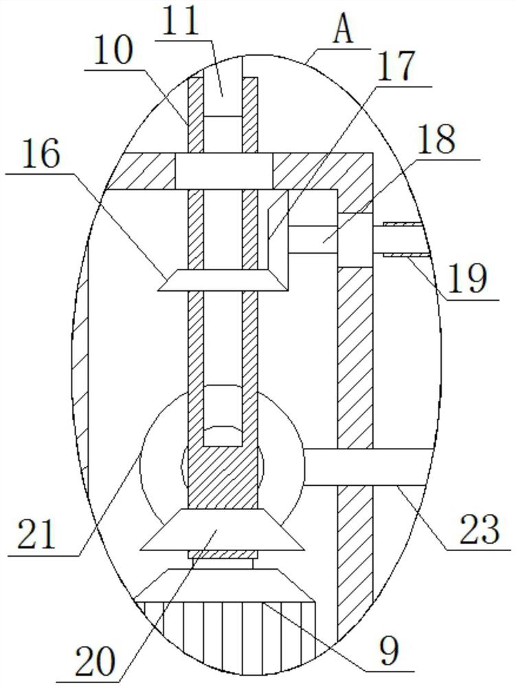
[0036] refer to Figure 5-6, the difference from Embodiment 1 is that the motion mechanism includes a third bevel gear 16, the third bevel gear 16 is fixedly connected with the rotating rod 10, the third bevel gear 16 is meshed with a fourth bevel gear 17, and the fourth bevel gear 17 is A second rectangular rod 18 is fixedly installed, and a rotary rod 19 is slidably installed on the second rectangular rod 18. The rotary rod 19 is fixedly connected with one of the two circular plates 7, and the first gear is fixedly installed on the rotary rod 10. 26. A second gear 27 is meshed with the first gear 26, and a round shaft 28 is fixedly installed on the second gear 27. A center plate 23 is slidably installed in the housing 1, and the round shaft 28 is slidingly connected with the inner wall of the center plate 23. The plate 23 is fixedly connected with the base 4 .

[0037] Working principle: when in use, open the warehouse door 25, start the cylinder 2 to control the limit box ...


PUM


Abstract

The invention belongs to the technical field of deburring equipment, particularly relates to automatic high-pressure flushing deburring equipment for automobile parts, and aims to solve the problems of low grinding efficiency and need of independent flushing in the prior art, the following scheme is provided: the automatic high-pressure flushing deburring equipment comprises a shell, an air cylinder is arranged in the shell, and a limiting box is fixedly mounted on a telescopic rod of the air cylinder; a base is slidably mounted in the shell, a fixing plate is fixedly mounted on the base, a clamping plate is slidably mounted on the base, circular plates are rotatably mounted on the fixing plate and the clamping plate, a screw is in threaded connection with the base, the screw is rotatably connected with the clamping plate, and a grinding mechanism is arranged in the shell and comprises a rotating rod. According to the grinding device, the grinding efficiency can be improved, automatic flushing can be achieved, time is saved, the machining efficiency is improved, use is easy, and operation is convenient.

Description

technical field [0001] The invention relates to the technical field of deburring equipment, in particular to an automatic high-pressure flushing and deburring equipment for auto parts. Background technique [0002] Auto parts are the units that constitute the whole of auto parts processing and the products that serve the processing of auto parts. As the foundation of the auto industry, auto parts are a necessary factor to support the sustainable and healthy development of the auto industry. In particular, the current independent development and innovation in the auto industry is vigorously and vigorously carried out, and it needs a strong parts system to support it. During the production of auto parts, there will be a lot of burrs on the surface, and deburring equipment is needed to remove these burrs. Avoid affecting the operation of the car. [0003] Many of the grinding equipment in the prior art require manual grinding, the grinding efficiency is low, and dust will be g...

Claims


Application Information

Patent Timeline
Patent Type & Authority Applications(China)
IPC IPC(8): B24B9/00B24B41/06B24B47/12B24B47/14B24B47/16B24B55/06
CPCB24B9/00B24B47/14B24B47/16B24B41/061B24B47/12B24B55/06
Inventor 纪文昌钱阿芳
Owner 润斯普瑞超声科技(苏州)有限公司
Learn More