Reed monitoring assembly, drawing-in machine incorporating such a reed monitoring assembly and process for monitoring a reed with such a reed monitoring assembly

a technology of reed monitoring and assembly, which is applied in the direction of auxiliaries, textiles and papermaking, weaving, etc., can solve the problems of reed being damaged or worn, presenting irregularities, and reed being dirty

Pending Publication Date: 2022-08-18
STAUBLI SARGANS AG
View PDF0 Cites 0 Cited by
  • Summary
  • Abstract
  • Description
  • Claims
  • Application Information

AI Technical Summary

Problems solved by technology

During its lifetime, a reed can be damaged or worn, to the point that it presents irregularities, for instance in terms of reed gap thickness, dent thickness, dent angle, dent density or that it includes bent dents or loose dents.
Moreover, a reed can be dirty after a certain period of time.
Bad reed quality and reed dirtiness may cause faults on a fabric woven on a weaving loom.
Such a check is not done systematically, for each warp change, since it is time consuming and requires a highly qualified...

Method used


Image

  • Reed monitoring assembly, drawing-in machine incorporating such a reed monitoring assembly and process for monitoring a reed with such a reed monitoring assembly
  • Reed monitoring assembly, drawing-in machine incorporating such a reed monitoring assembly and process for monitoring a reed with such a reed monitoring assembly
  • Reed monitoring assembly, drawing-in machine incorporating such a reed monitoring assembly and process for monitoring a reed with such a reed monitoring assembly

Examples


first embodiment

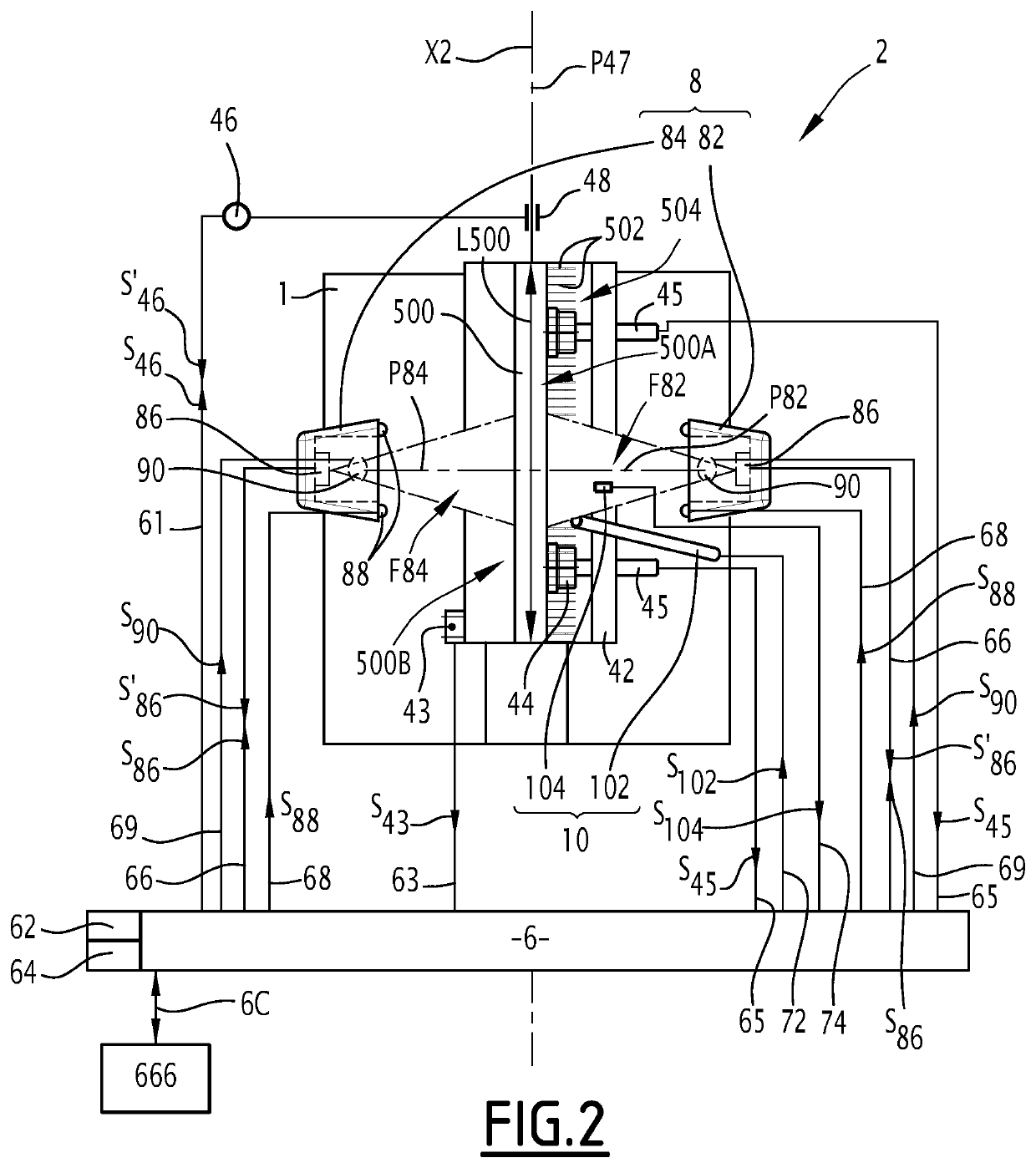
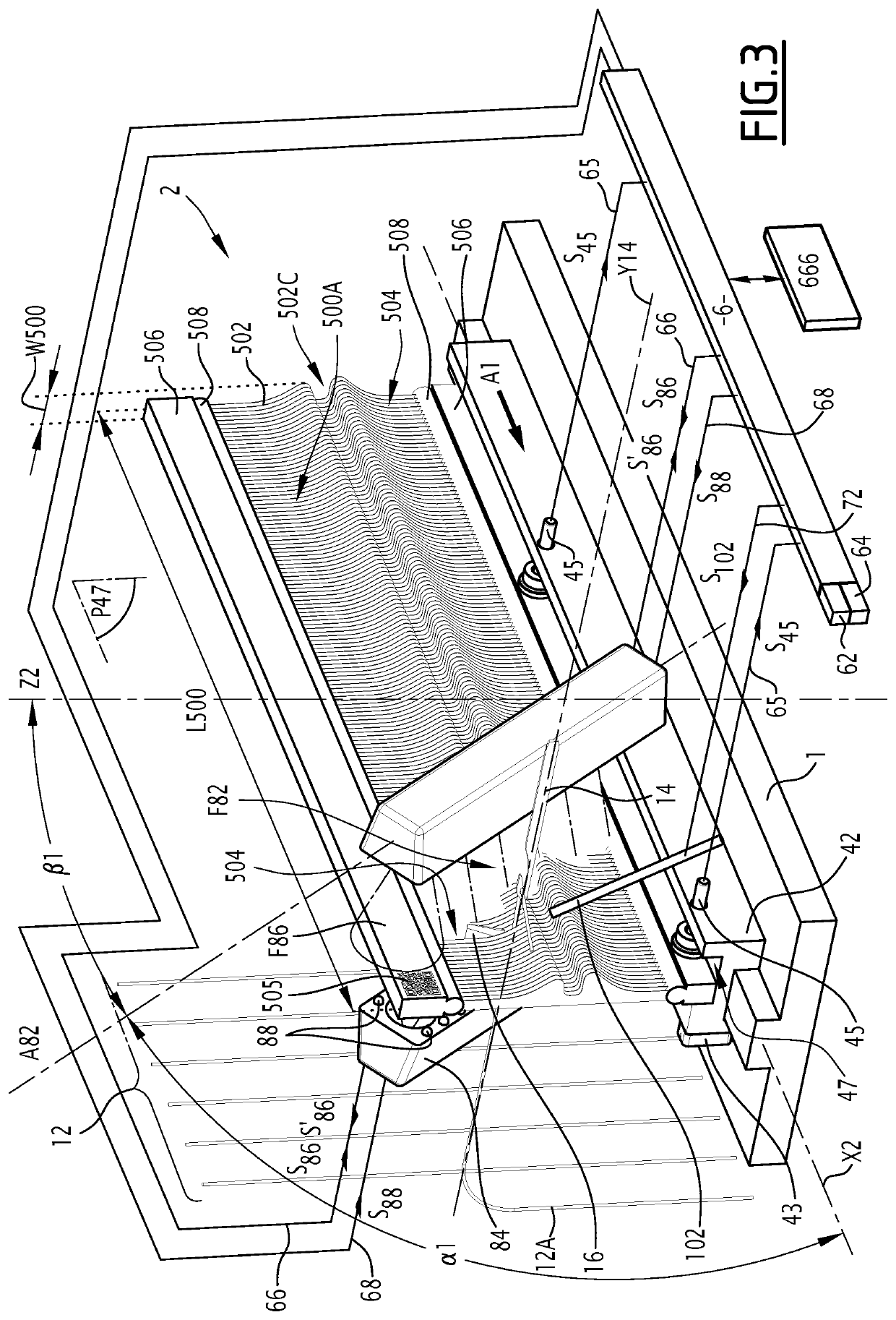
[0090]In the example of FIGS. 3 and 4, angles α1 and α2 are identical and angles β1 and β2 are identical. Thus, the two camera arrays 82 and 84 face each other along the transverse direction and central planes P82 and P84 defined as in the first embodiment are superimposed. This is advantageous, in order for the two camera arrays 82 and 84 to check the same dents 502 and reed gaps 504 at the same time. However, this is not compulsory.

[0091]Weaving reed 500 bears an identification mark 505, in the form of a QR code printed on its upper profile 506 preferably on the first or last 10 centimeters along the reed length L500, and the sensor 86 of the first camera array 82 looking at the upper profile 506 is capable of reading this identification mark and forwarding the corresponding information to controller 6, within signal S′86.

[0092]In the first two embodiments of the invention, the reed monitoring assembly 2 has a non-represented touch screen for inputting some information about the r...

second embodiment

[0093]If a reed identification marking, like QR code 505 of the second embodiment, is provided, it can be used for automatically identifying the reed 500 to be monitored. This also belongs to the inputs for the reed monitoring device.

[0094]In addition, the operator for the monitoring process can input the following information:

[0095]reed settings, such as reed density;

[0096]monitoring speed, that is a choice between a case where the reed is carefully inspected, at low speed, and a case where the reed is basically inspected, at high speed;

[0097]customers threshold such as maximum acceptable reed wear and tear to be authorized for further use of the weaving reed 500, maximum acceptable depth of a scratch / groove on a dent 502 to be authorized for further use of the reed, etc ...

[0098]drawing-in pattern, in particular the number of warp yarns to be inserted per reed gap 504, the type of warp yarns, the dimensions of the drawing-in hook 14 and of the blade 16.

[0099]When starting the reed...

third embodiment

[0167]In the invention, represented on FIGS. 5 and 6, elements similar to ones of the first two embodiments have the same references and are not described in detail.

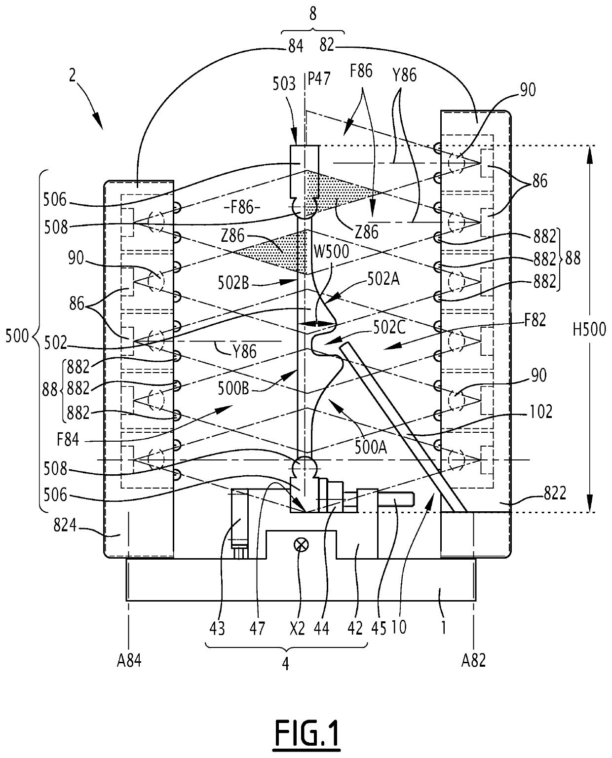
[0168]Here-after, mainly the differences with respect to the first embodiment are described. In this third embodiment, the reed includes straight dents 502 which do not form a tunnel similar to tunnel 502C of the first two embodiments. No airflow measuring device is provided.

[0169]The reed monitoring assembly 2 of this third embodiment is independent from a drawing-in machine and can be used with a weaving reed 500 mounted on a weaving loom, with a reed mounted on a drawing-in machine, with a reed mounted on a reed denting machine or with a reed mounted on a fixed reed holder 50, as represented on FIGS. 5 and 6.

[0170]The weaving reed 500 is preferably installed in a vertical position, with its height H500 vertical. Here, the reed 500 is static. In other words, it does not move relative to the space around during the reed...


PUM


Abstract

A reed monitoring assembly to monitor a weaving reed that have dents juxtaposed along longitudinal direction of the weaving reed. The dents define height direction of the reed and reed gap. The assembly includes an optical device with a first camera array, for taking images of a first portion of the weaving reed, and facing the first longitudinal side of the weaving reed, an illumination device to illuminate the first portion of the weaving reed, and a second camera array, for taking images of a second portion of the weaving reed, and facing the opposite longitudinal side of the weaving reed. The reed monitoring assembly also includes a controller, for controlling the optical device and for receiving image data from the device, and mounting means allowing a relative movement between the weaving reed and the optical device, along an axis parallel to the longitudinal direction of the weaving reed.

Description

TECHNICAL FIELD OF THE INVENTION[0001]This invention relates to a reed monitoring assembly for monitoring a weaving reed for a weaving loom. This invention also relates to a drawing-in machine including, amongst others, such a reed monitoring assembly. Finally, the invention relates to a process for monitoring a reed for a weaving loom with a reed monitoring assembly.[0002]The technical field of the invention is the one of weaving reed monitoring and measurement.BACKGROUND OF THE INVENTION[0003]In the field of weaving, it is known to use a reed in order to guide warp yarns near the shedding zone of a loom and in order to beat up, by front edges of the reed dents, the weft yarn inserted between the warp yarns against the fabric woven on the weaving loom. During its lifetime, a reed can be damaged or worn, to the point that it presents irregularities, for instance in terms of reed gap thickness, dent thickness, dent angle, dent density or that it includes bent dents or loose dents. Mo...

Claims


Application Information

Patent Timeline
IPC IPC(8): D03J1/24D03J1/14
CPCD03J1/24D03J1/14
Inventor ROMAGNA, HANSPETERWOLF, MARKUS
Owner STAUBLI SARGANS AG
Why Eureka
Try Eureka