Roller screw

a roller screw and mechanism technology, applied in mechanical equipment, gearing, hoisting equipment, etc., can solve the problem of limited load capacity of roller screw mechanisms

Active Publication Date: 2013-06-20
AB SKF
View PDF29 Cites 19 Cited by
  • Summary
  • Abstract
  • Description
  • Claims
  • Application Information

AI Technical Summary

Benefits of technology

[0008]More particularly, the aim of the present invention is to provide a roller screw mechanism wherein, for a given diameter, the load capacity is increased.

Problems solved by technology

This requires the load capacities of the roller screw mechanisms to be limited such as to prevent the occurrence of stress concentration.

Method used


Image

  • Roller screw
  • Roller screw
  • Roller screw

Examples


Embodiment Construction

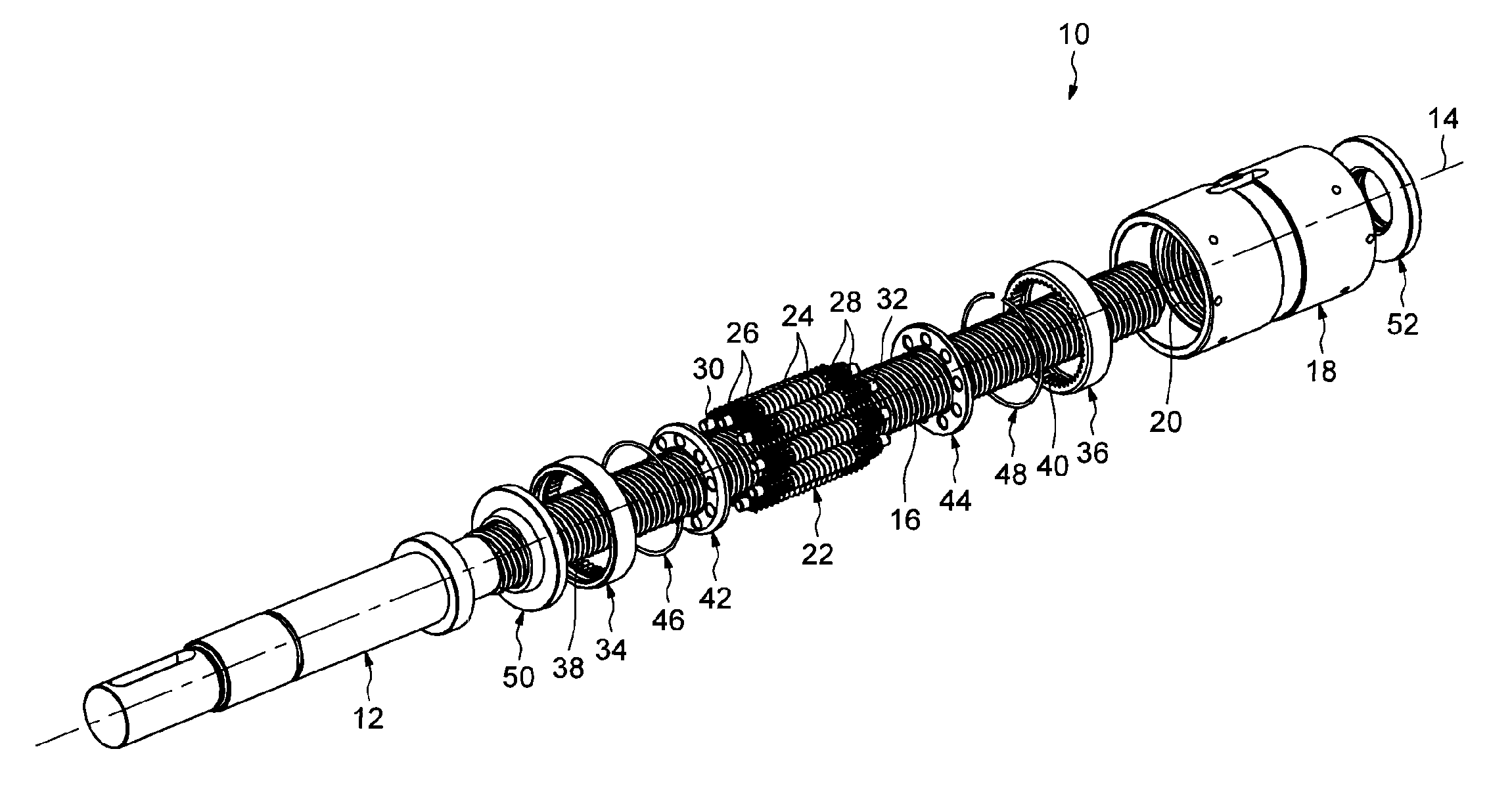
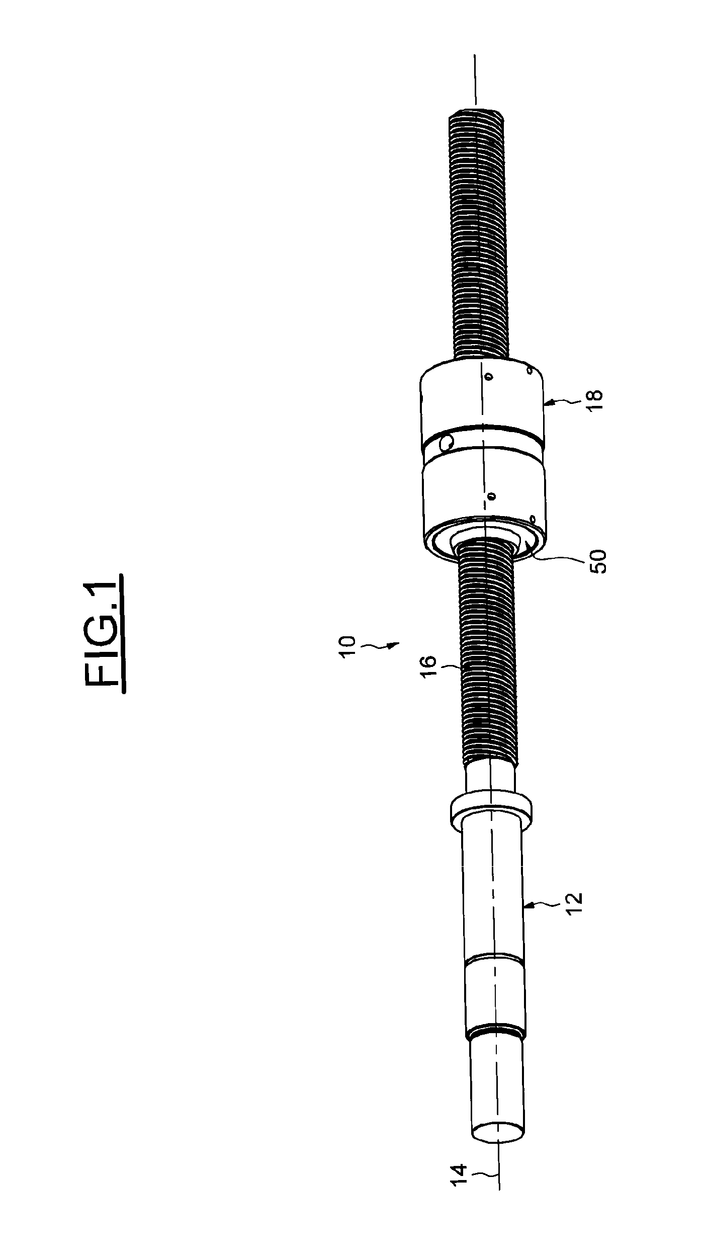
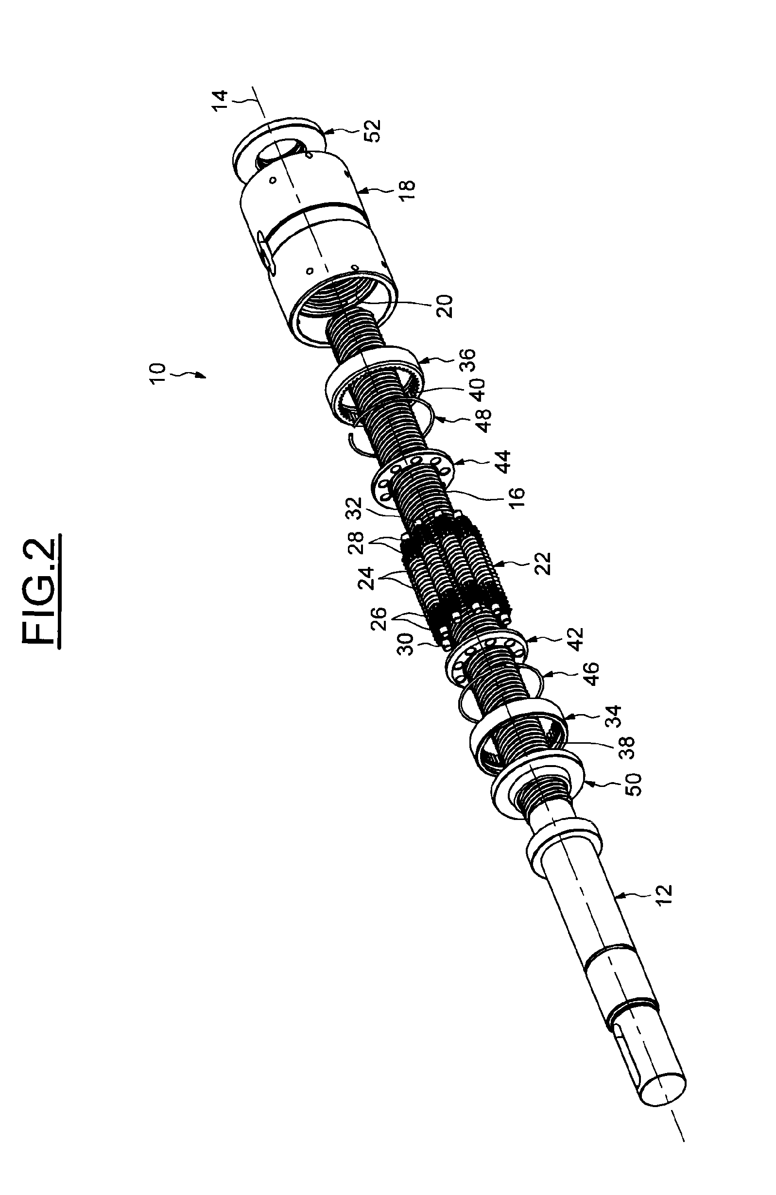
[0022]In FIGS. 1-3, a roller screw mechanism, which is referenced 10 as a whole, includes a screw 12, with an axis 14, which screw is provided with an external thread 16, a nut 18 mounted coaxially about the screw 12 and provided with an internal thread 20, the internal diameter of which is greater than the external diameter of the external thread 16, and a plurality of longitudinal rollers 22 arranged radially between the screw and the nut. The screw 12 extends longitudinally through a cylindrical bore of the nut 18 on which the internal thread 20 is formed.

[0023]The rollers 22 are identical to each other and are distributed in a regular manner about the screw 12. Each roller 22 extends along an axis 22a which is coaxial with the axis 14 of the screw and includes an external thread 24 engaging the thread 16 of the screw and the thread 20 of the nut. The thread of the screw 12 and the nut 18 each include five thread start lead-ins and the thread of each roller 22 includes one thread...


PUM


Abstract

The roller screw mechanism is provided with a screw including an external thread, with a nut arranged about and coaxial with said screw, the nut including an internal thread, and with a plurality of rollers inserted between the screw and the nut and each including an external thread engaging the external and internal threads of said screw and of said nut. The screw is axially moveable in relation to the rollers. The flanks of the thread of the screw have a concave profile in cross section.

Description

CROSS-REFERENCE TO RELATED APPLICATION[0001]This US Non-Provisional Utility application claims the benefit of copending French Patent Application Serial No. FR1161806 filed on Dec. 16, 2011, which is incorporated herein in its entirety.FIELD OF THE INVENTION[0002]The present invention relates to the field of roller screw mechanisms for transforming a rotary movement into a linear translation movement, and vice versa.BACKGROUND OF THE INVENTION[0003]One mechanism is provided with a screw including an external thread, with a nut arranged about the screw and including an internal thread, and with a plurality of longitudinal rollers engaging the external and internal threads of the screw and of the nut. In comparison with a ball screw mechanism, the main advantage of a roller screw mechanism is greater admissible load capacities.[0004]A first type of roller screw mechanism includes rollers having an external thread engaging the external and internal threads of the screw and of the nut. ...

Claims


Application Information

Patent Timeline
Patent Type & Authority Applications(United States)
IPC IPC(8): F16H25/22
CPCF16H25/2252Y10T74/19795Y10T74/18576F16H25/2266
Inventor BUVRIL, GERARDGIRAUDEAU, JEAN-PAULKREBS, PHILIPPLECLUSE, SEBASTIEN
Owner AB SKF
Why Eureka
Try Eureka