Arrangement structure for charging port cover

Inactive Publication Date: 2013-06-20
NISSAN MOTOR CO LTD
View PDF3 Cites 24 Cited by
  • Summary
  • Abstract
  • Description
  • Claims
  • Application Information

AI Technical Summary

Benefits of technology

[0005]The present invention has been made in view of the above-described conventional problem. It is an object of th

Problems solved by technology

However, a process of attaching the cover to the lid in the opened state

Method used


Image

  • Arrangement structure for charging port cover
  • Arrangement structure for charging port cover
  • Arrangement structure for charging port cover

Examples


Example

[0019]Hereinafter, an embodiment of the present invention will be explained in detail with reference to the drawings. Although the following embodiment exemplifies an electric vehicle, the present invention is also applicable to a so-called hybrid vehicle.

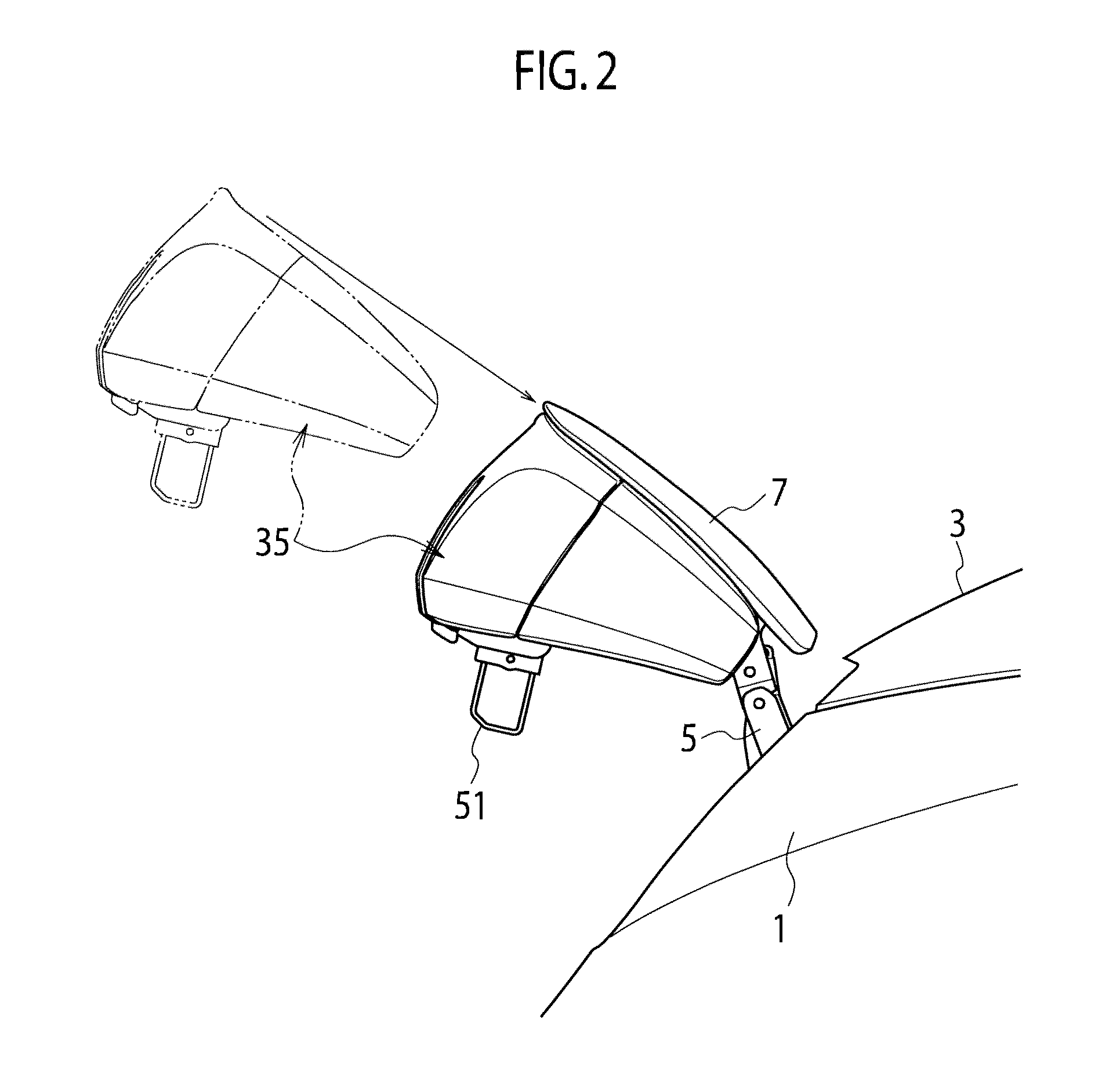
[0020]As shown in FIG. 1 to FIG. 4, a bumper 1 is provided along the width of the front portion of a vehicle. A hood 3 is provided on the rear side of the bumper 1 to cover a motor room. In the centre portion of the vehicle width direction on the front side of the hood 3, a lid 7 is provided such that it is openable and closable in a vertical direction via lid-side hinges 5 provided on both sides of the lid 7. The lid 7 is formed approximately in a trapezoidal shape in a planar view and has a rear edge 9 and a front edge 11 shorter than the rear edge 9. Side edges 13, 13 obliquely extend to the front edge 11 so that the lid 7 is formed in a forward tapered shape.

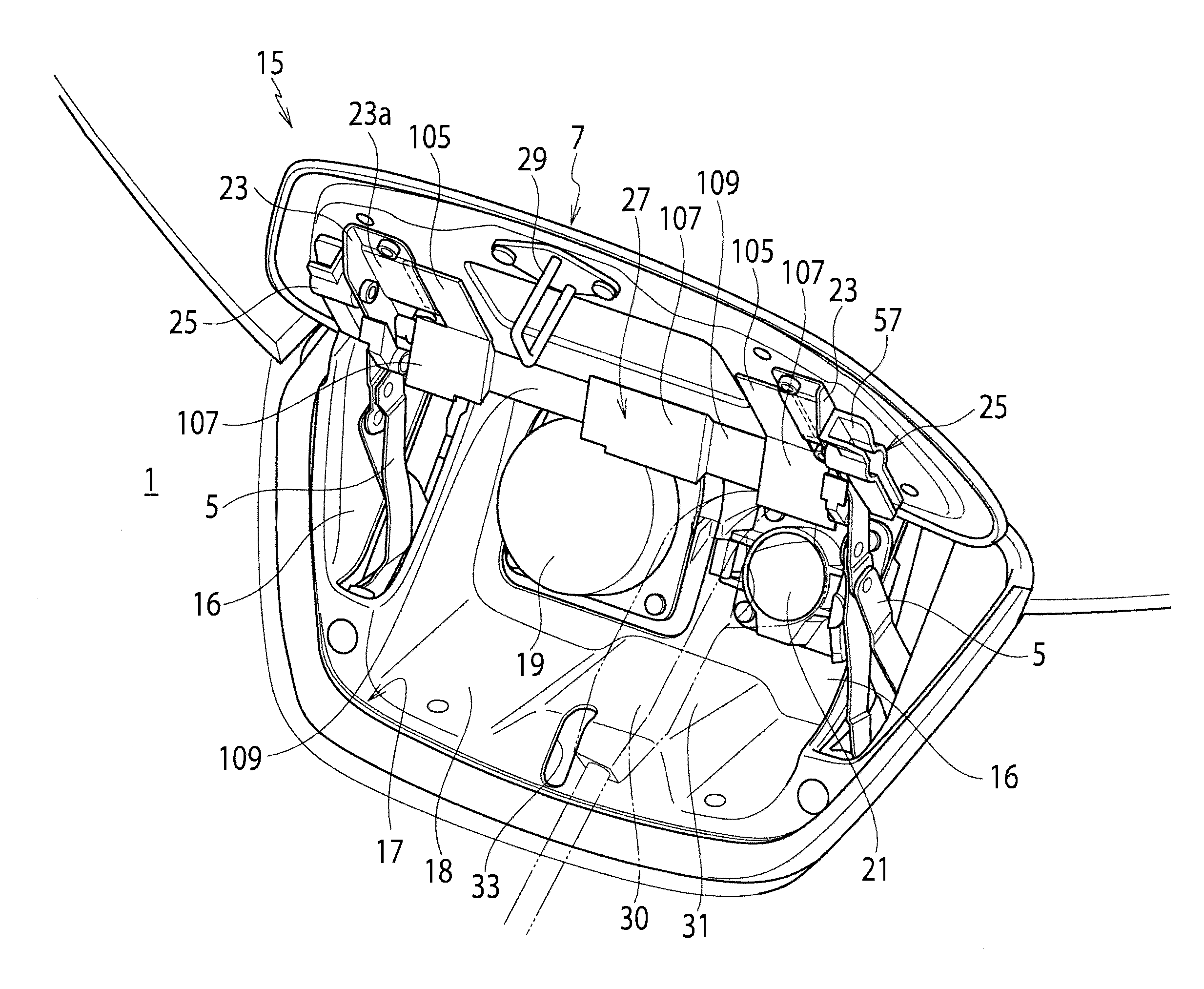
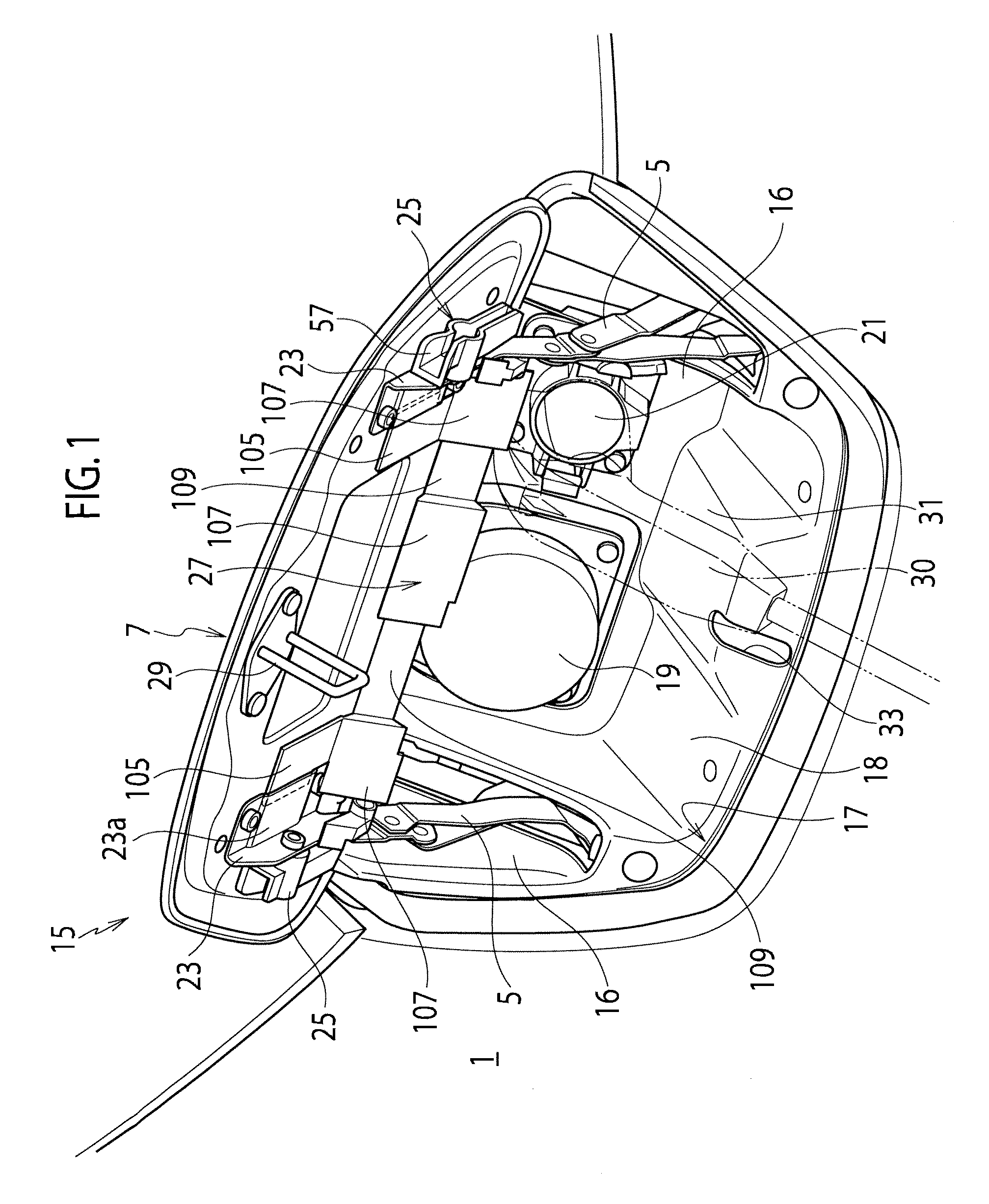
[0021]As shown in FIG. 1, a charging port 15 is provided in the front ...


PUM


Abstract

An arrangement structure for a charging port cover includes a charging port (15) having a normal charging inlet (21) in a charging port opening portion (17). a lid (7) that covers the charging port opening portion (17) and is openable and closable on a vehicle body, and a charging port cover (35) attached to the lid (7) in an opened state to cover open sections between the charging port opening portion (17) and the lid (7). The charging port cover (35) is attached to the lid (7) via a lid-side striker (29) serving as an engaging member.

Description

TECHNICAL FIELD[0001]The present invention relates to an arrangement structure for a charging port cover attached to a charging port on a vehicle such as an electric vehicle during charging.BACKGROUND ART[0002]Vehicles such as electric vehicles and so-called hybrid vehicles are commonly provided with a charging port to charge an on-board battery. The charging port has a charging inlet connected to the on-board battery, and an openable and closable lid that covers the charging inlet. When the lid is open, a charging gun (a paddle) is inserted in the charging inlet to charge the battery (for example, refer to Patent Document 1).CITATION LISTPatent Literature[0003]Patent Document 1: Japanese Patent Unexamined Publication No. H11-318004SUMMARY OF INVENTION[0004]However, a process of attaching the cover to the lid in the opened state is complicated since the cover is a separated part from a vehicle body.[0005]The present invention has been made in view of the above-described conventional...

Claims


Application Information

Patent Timeline
IPC IPC(8): H02G3/14
CPCB60L11/1818B60L11/185H01R13/447Y02T10/7005Y02T10/7088Y02T90/121B60K1/04Y02T90/14H02G3/14H01M2220/20B60L2270/32B60L2270/34Y02T90/128B60K2015/0435B60K2015/0454B60K2015/053B60K2015/0553B62D25/24B60K15/04B60L53/11B60L53/16H01R13/6395Y02E60/10Y02T10/70Y02T10/7072Y02T90/12
Inventor YAMAMARU, JUNICHITAKASHIMA, DAISUKE
Owner NISSAN MOTOR CO LTD
Why Eureka
Try Eureka