Broadband planar inverted-f antenna

Inactive Publication Date: 2013-06-20
ARCADYAN
View PDF4 Cites 1 Cited by
  • Summary
  • Abstract
  • Description
  • Claims
  • Application Information

AI Technical Summary

Benefits of technology

[0007]The invention is directed to a broadband planar inverted-F antenna. An indented structure is formed in a planar radiation conductor of the broadband planar inverted-F antenna for generating a travelling wave radiation after signals are fed to the antenna. The distance between two opposite sides of the indented structure is gradually increased from an o

Problems solved by technology

However, under the miniaturizing and thinning trend of TV screen, if the wireless module still uses the planar inverte

Method used


Image

  • Broadband planar inverted-f antenna
  • Broadband planar inverted-f antenna
  • Broadband planar inverted-f antenna

Examples


Embodiment Construction

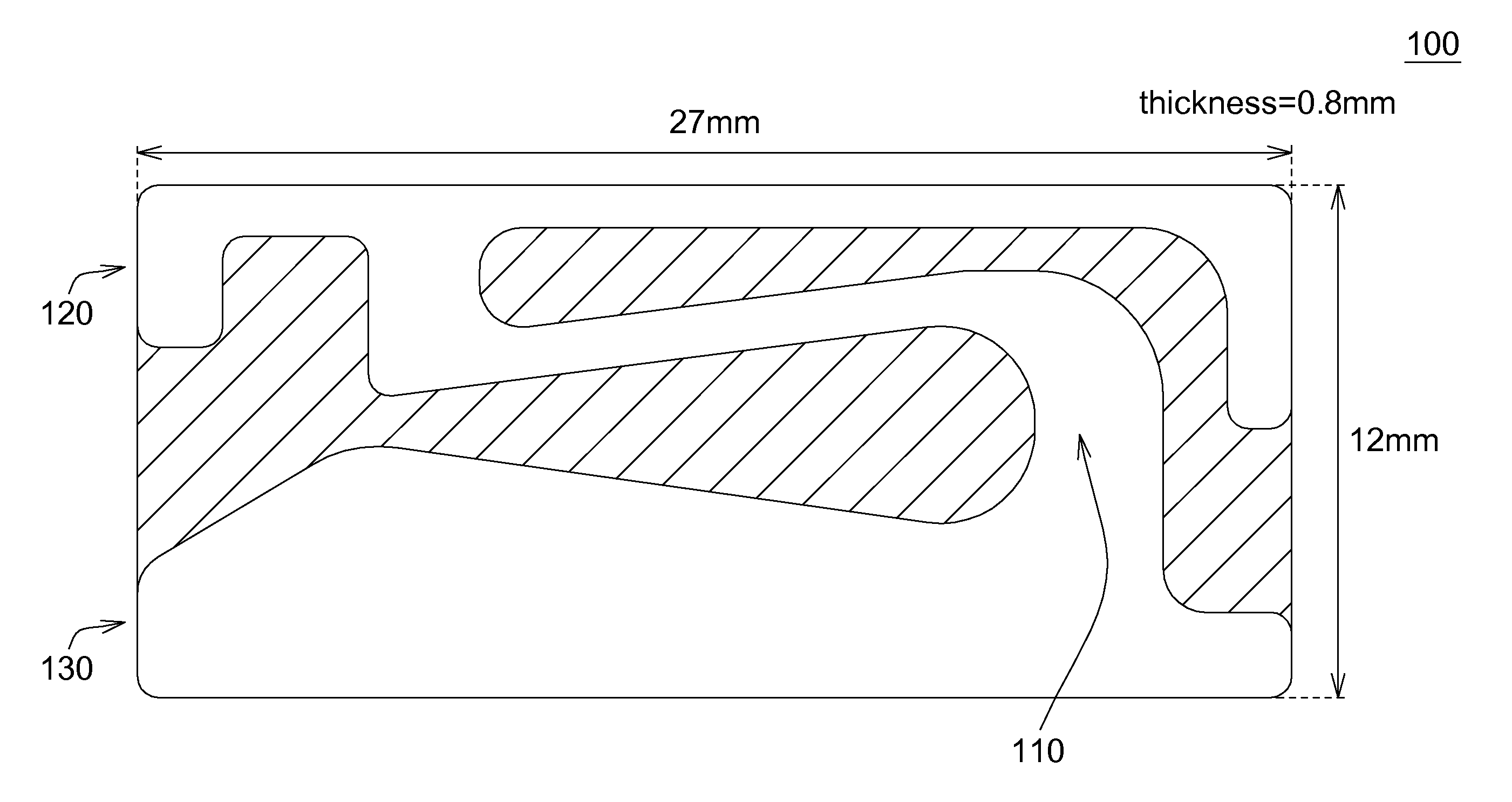
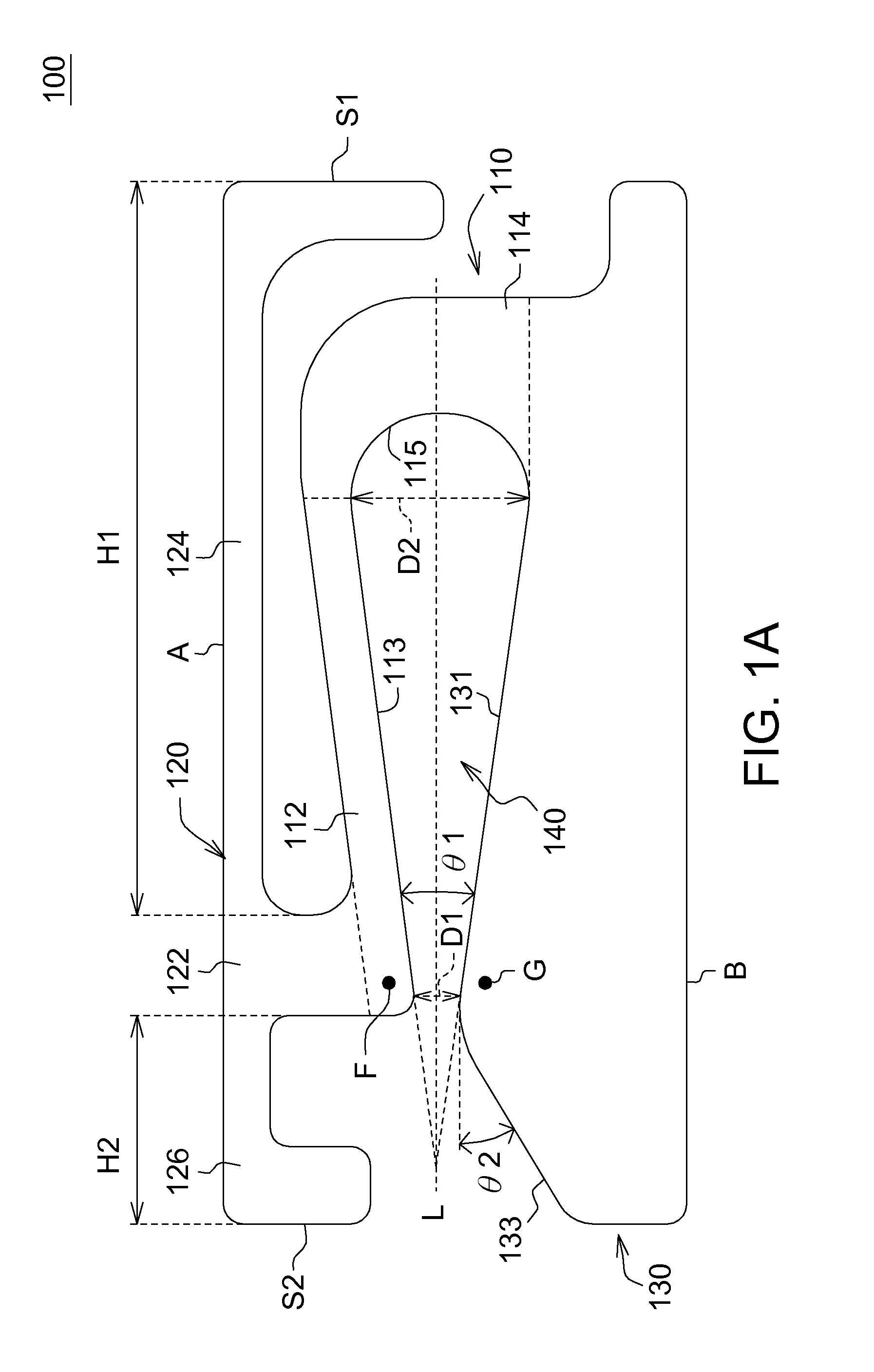
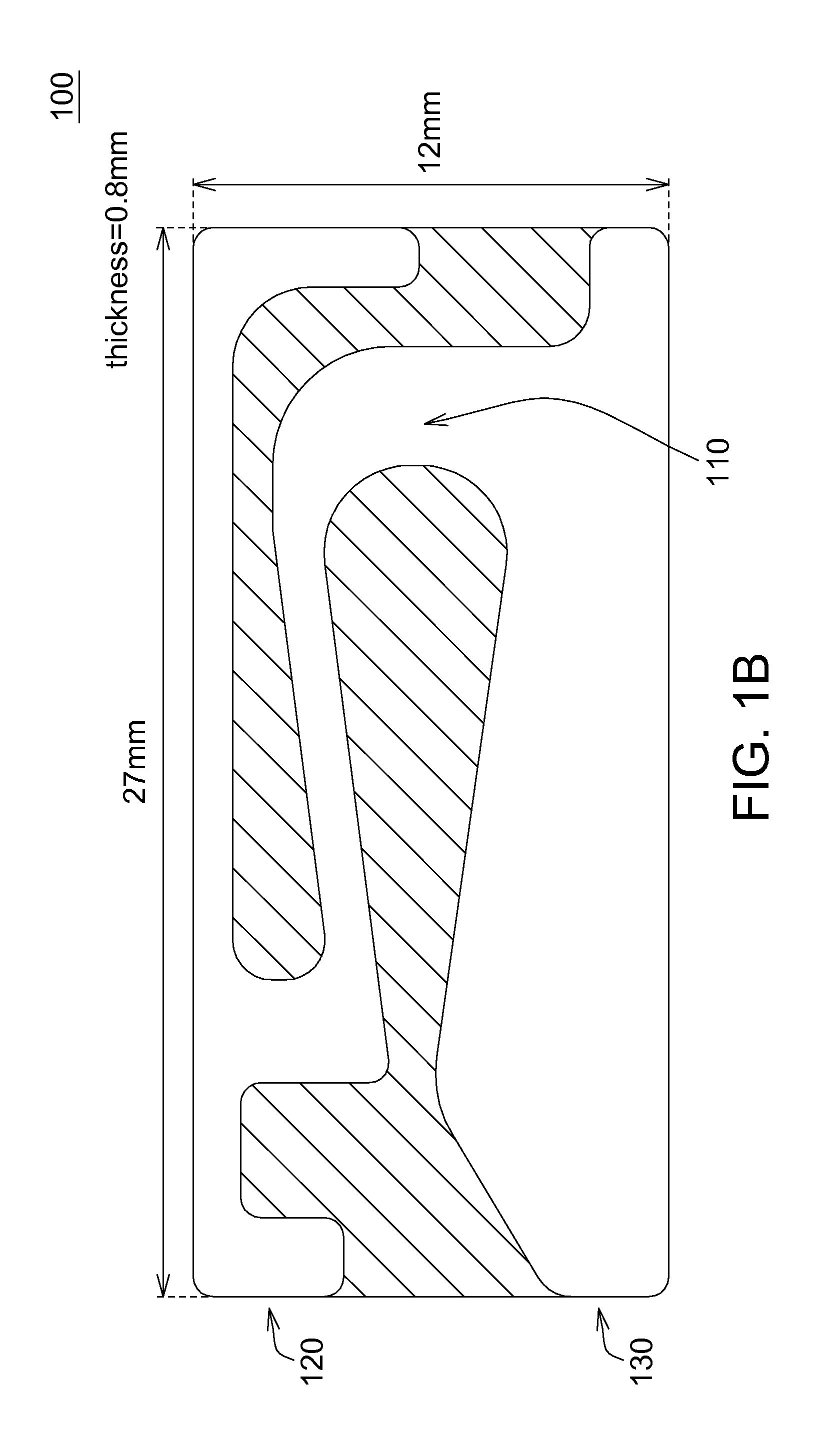
[0018]The invention is directed to a dual-band broadband planar inverted-F antenna. A radiation arm and an indented structure are formed in a planar radiation conductor of the planar inverted-F antenna for generating a resonance standing wave radiation and a travelling wave radiation respectively after signals are fed to the antenna. The distance between two opposite sides of the indented structure is gradually increased from an opening of the indented structure towards the closed base of the indented structure for increasing the signal bandwidth of the travelling wave radiation. Therefore, a thin planar inverted-F antenna, which has big bandwidth and can be built on the thin frame of TV screen and satisfy the bandwidth requirement in WLAN communication, can thus be provided.

[0019]Referring to FIG. 1A, a structural diagram of a broadband planar inverted-F antenna according to an exemplary embodiment of the invention is shown. The planar inverted-F antenna 10 is closely appressed to ...


PUM


Abstract

A broadband planar inverted-F antenna includes a first radiation conductor, a second radiation conductor and a third radiation conductor. The first radiation conductor includes a first inclined-plane portion and a feeding point. The feeding point is located at one end of the first inclined-plane portion. The second radiation conductor is connected to the first radiation conductor at the feeding point. The third radiation conductor is connected to the first radiation conductor, and includes a second inclined-plane portion and a ground point. The second inclined-plane portion is separated from and facing to the first inclined-plane portion. The ground point is located at one end of the second inclined-plane portion and facing to the feeding point, wherein the distance between the first inclined-plane portion and the second inclined-plane portion is gradually increased from the part near the feeding point along a direction departing from the feeding point.

Description

[0001]This application claims the benefit of Taiwan application Serial No. 100146643, filed Dec. 15, 2011, the subject matter of which is incorporated herein by reference.BACKGROUND OF THE INVENTION[0002]1. Field of the Invention[0003]The invention relates in general to a broadband planar inverted-F antenna (PIFA), and more particularly to a dual-band and broadband planar inverted-F antenna built in thin frame TV.[0004]2. Description of the Related Art[0005]Wireless communication has gained booming development in recent years. In response to the trend of miniaturization in many communication products, the antenna needs to be down-sized and possess an embedded architecture so as to provide an aesthetic appearance to the products. In comparison to the monopole antenna and the inverted-F antenna, the planar inverted-F antenna has the advantages of smaller size and bigger. Through suitable design with the radiation conductor, the planar inverted-F antenna is able to receive dual-band an...

Claims


Application Information

Patent Timeline
IPC IPC(8): H01Q1/36H01Q5/10H01Q5/15
CPCH01Q1/22H01Q1/48H01Q5/364H01Q1/243H01Q1/38H01Q9/42
Inventor CHENG, SHIH-CHIEHLO, KUO-CHANG
Owner ARCADYAN
Why Eureka
Try Eureka