Three-way connector for connecting weft feeders of textile machines to a serial bus, and a control system based thereon

a technology of serial bus and weft feeder, which is applied in the direction of weaving, looms, coupling device connections, etc., can solve the problems of affecting the operation of personnel, increasing the bulk of cable bundles, and affecting the appearance of textile machines,

Inactive Publication Date: 2005-02-03
L G L ELECTRONICS
View PDF13 Cites 3 Cited by
  • Summary
  • Abstract
  • Description
  • Claims
  • Application Information

AI Technical Summary

Benefits of technology

[0007] It is now the main object of the invention to provide a three-way connector making it feasible to set up a control system for weft feeders of a textile machine, particularly a knitting machine, which system will eliminate the above drawbacks and overcome the above limitations.
[0008] More particularly, it is the aim of the invention to provide a control system by which several hundreds weft feeders can be addressed without error, while the bulk of the system cables is reduced and the signal bandwidth is increased.
[0009] It is another aim of the invention to provide a three-way connector by means of which the above control system may be set up easily and conveniently.

Problems solved by technology

As the number of slave weft feeders increases (which number in large machines may reach and exceed a hundred), the number of cables in the star connection increases proportionally, thereby also increasing the bulk of the cable bundles and making it difficult to neatly arrange them.
This situation not only imparts an unpleasant look to the machines, but also may hinder the operation of the personnel.
Further, as persons skilled in the art will appreciate, a long cable may create problems due to the reflections of the signal traveling on the bus, and this circumstances places serious limits to the bandwidth, i.e. to the signal transmission speed along the bus.
Another and even more serious drawback of the star-connected bus distribution on machines having a large number of weft feeders concerns the addressing of the receivers of the respective weft feeders.
However, the analog character of this approach is only suitable for addressing half a score weft feeders.

Method used


Image

  • Three-way connector for connecting weft feeders of textile machines to a serial bus, and a control system based thereon
  • Three-way connector for connecting weft feeders of textile machines to a serial bus, and a control system based thereon
  • Three-way connector for connecting weft feeders of textile machines to a serial bus, and a control system based thereon

Examples


Embodiment Construction

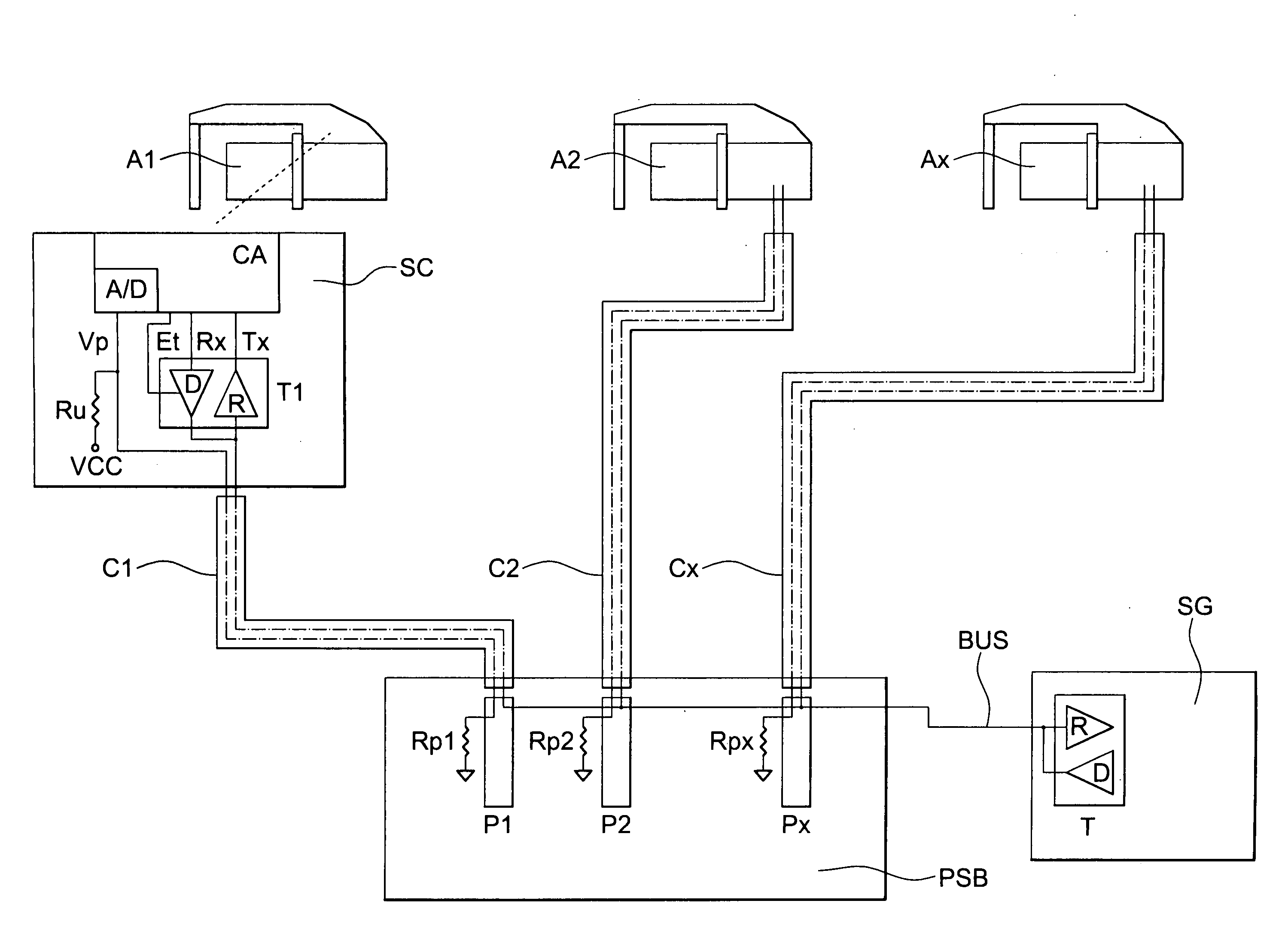
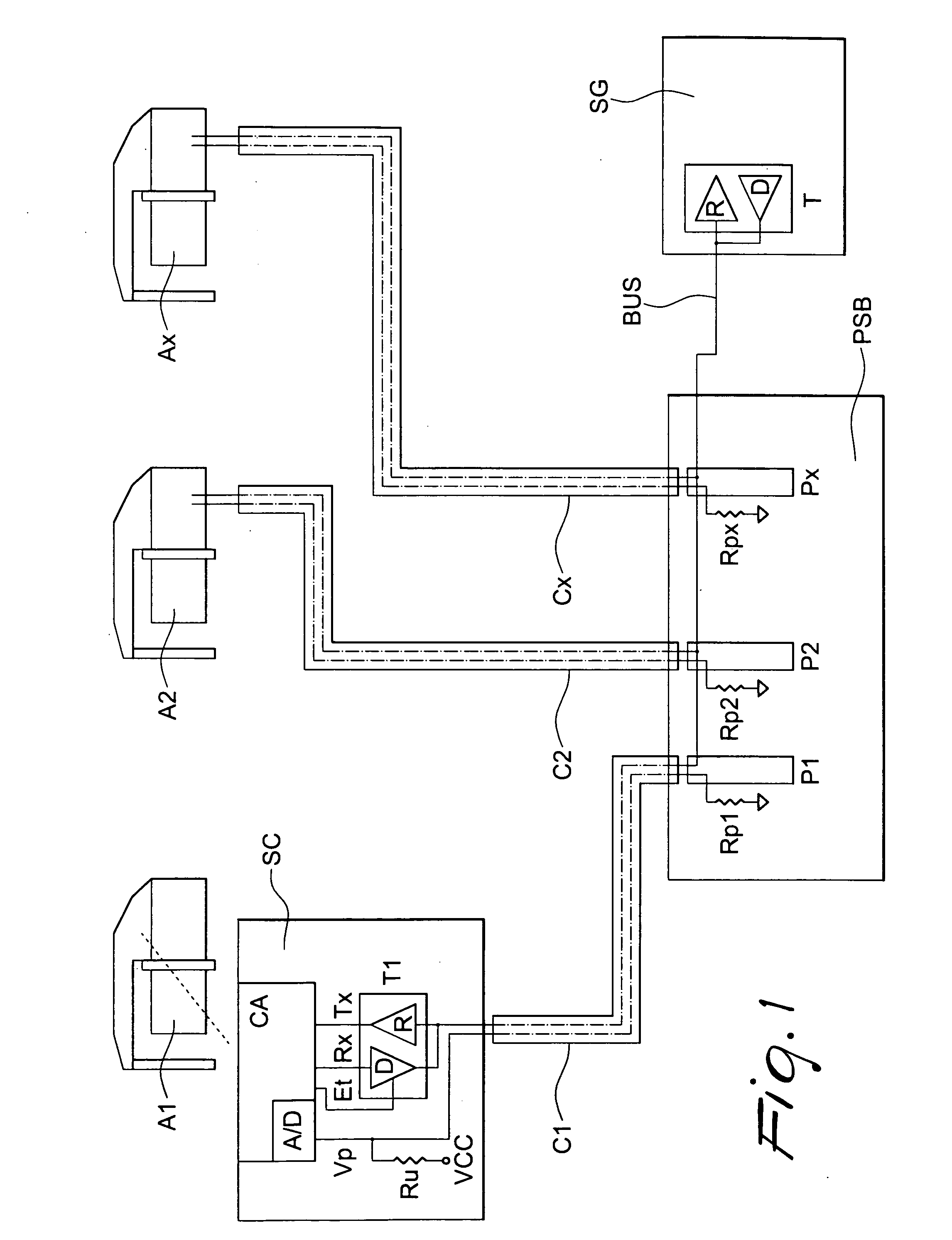
[0016] With reference to FIG. 1, in a system of the prior art a plurality of weft feeders of a textile machine, such as A1, A2, Ax, are connected by respective connection cables C1, C2, Cx to a distribution box PBS and from there to a master managing unit SG for the machine, via a bidirectional serial differential bus BUS, typically RS485 or CAN Bus. Within managing unit SG, bus BUS leads to a receiver R and to a driver D. Within box PBS, the bus forks out in star-fashion to cables C1, C2, Cx, via respective connectors P1, P2, Px leading to respective electronic cards of weft feeders A1, A2, Ax; for simplicity, only a card SC for weft feeder A1 is shown. Card SC typically includes a microcontroller CA managing the so-called transceiver T1 comprising a receiver R for receiving serial digital signals from the bus and transferring them as Tx to microcontroller CA, and a driver D for receiving signals Rx from CA and transmitting them onto the bus. Usually, an enabling signal Et is also ...


PUM


Abstract

The three-way connector comprises a first, a second and a third gates directly connected to one another. The first and second gate are pluggable onto respective spans of a bus, and the third gate is connectable to a weft feeder. The three-way connector further comprises a permanent memory containing an identifying code for the associated weft feeder. A managing unit drives a serial bus to which a plurality of weft feeders are connected. The serial bus comprises the cable spans, serially connected to one another through the first and second gates of the connectors, the weft feeders being connected to respective third gates of the connectors.

Description

[0001] This invention is concerned with a three-way connector for connecting a serial bus with a weft feeder for textile machines, particularly knitting machines, and with a weft feeder control system that is implemented by means of the connector. BACKGROUND OF THE INVENTION [0002] In modern textile machines, a plurality of weft feeders are slave to a master managing unit, from which they receive individual control signal or programming signals for individual parameter, and to which they transmit information signals concerning the state of the machine or process variables. This bidirectional conversation has typically taken place via a star connection between the managing unit and the individual weft feeders, and the connection, as a rule, has used differential-type buses, say according to standards RS485 or CAN. [0003] As the number of slave weft feeders increases (which number in large machines may reach and exceed a hundred), the number of cables in the star connection increases ...

Claims


Application Information

Patent Timeline
Patent Type & Authority Applications(United States)
IPC IPC(8): D04B15/48D04B35/00
CPCD04B35/00D04B15/482
Inventor PEDRINI, GIOVANNIGOTTI, LUCAVARISCHETTI, MAURO
Owner L G L ELECTRONICS
Why Eureka
Try Eureka