Daylight illumination apparatus

a technology of daylight illumination and apparatus, which is applied in the direction of lighting and heating apparatus, lighting applications, and using daylight, can solve the problems of complex technical problems such as the second light guide for transferring the light of the vessel to the rooms of the building, and achieve the effects of improving mimicry, reducing the probability of photoluminescent light, and improving mimicry

Inactive Publication Date: 2013-06-20
SIGNIFY HLDG BV
View PDF0 Cites 20 Cited by
  • Summary
  • Abstract
  • Description
  • Claims
  • Application Information

AI Technical Summary

Benefits of technology

[0025]a control unit for controlling the active compensation light source depending on the determined intensity. This allows providing a desired light intensity at the illumination location, even if the intensity of the daylight changes. Moreover, the intensity of the light from the active compensation light source can be adjusted to the intensity of the daylight, in particular, if the intensity of the daylight is reduced, the intensity of the active compensation light source can be reduced accordingly. This further improves the mimicry of direct natural daylight.
[0026]In an embodiment, the daylight illumination apparatus comprises a polarizer for polarizing at least one of the daylight and the photoluminescent light to a polarization being similar to the natural polarization of daylight. That means that the polarizer can polarize the daylight, which has been guided by the light guide, and / or the photoluminescent light emitted by the photoluminescent material. The polarizer can also be adapted to polarize compensation light, which may optionally be provided by an active compensation light source. This further improves the mimicry of the direct natural daylight.
[0027]It is preferred that the daylight illumination apparatus comprises a light guide entering probability reducing unit for reducing the probability of the photoluminescent light to enter the light guide. With respect to the optical path, the light guide entering probability reducing unit is preferentially arranged between the light guide and the photoluminescent material. The light guide entering probability reducing unit can be a multilayer dielectric reflector being adapted for allowing light coming out of the light guide to transmit through the multilayer dielectric reflector and for reflecting the photoluminescent light emitted by the photoluminescent material. The light guide entering probability reducing unit can also comprise a light expander for expanding the light guided by the light guide before meeting the photoluminescent material. In an embodiment, the light expander comprises a mixing chamber comprising a small entrance hole where light from the light guide enters, an exit window comprising the phosphor and a diffuse reflecting coating or layer on the remaining inner surface of the mixing chamber. In that way photoluminescent light that is emitted into the mixing chamber has a small chance to enter the light guide, and a high chance to be diffusely reflected towards the exit window. In a further embodiment, the light guide entering probability reducing unit comprises a transparent plate having two opposing main surfaces and side surfaces connecting the main surfaces, wherein the light guide and the transparent plate are adapted such that light leaving the light guide enters the transparent plate via a side surface of the transparent plate and that the light leaves the transparent plate via a main surface of the transparent plate, wherein the photoluminescent material is arranged on the main surface through which the light leaves the transparent plate. The transparent plate is preferentially transparent to visible light. In a further embodiment, the light guide entering probability reducing unit comprises a transparent plate having two opposing main surfaces and side surfaces connecting the main surfaces, wherein the light guide and the transparent plate are adapted such that light leaving the light guide enters the transparent plate via a side surface of the transparent plate and that the light leaves the transparent plate via a main surface of the transparent plate, wherein the photoluminescent material is incorporated into the transparent plate.
[0028]Since the light guide entering probability reducing unit reduces the probability of the photoluminescent light to enter the light guide, losses of the photoluminescent light caused by coupling the photoluminescent light into the light guide can be reduced, thereby further improving the illumination of the illumination location by the combination of daylight and photoluminescent light.

Problems solved by technology

This lighting system with the arrangement of the light collectors, the first light guides for transferring ambient light from the light collectors into the vessel, the white light sources for providing light within the vessel for compensating for absorption losses of the ambient light in the first light guides and the second light guides for transferring the light of the vessel to the rooms of the building is technically complex.

Method used


Image

  • Daylight illumination apparatus
  • Daylight illumination apparatus
  • Daylight illumination apparatus

Examples


Embodiment Construction

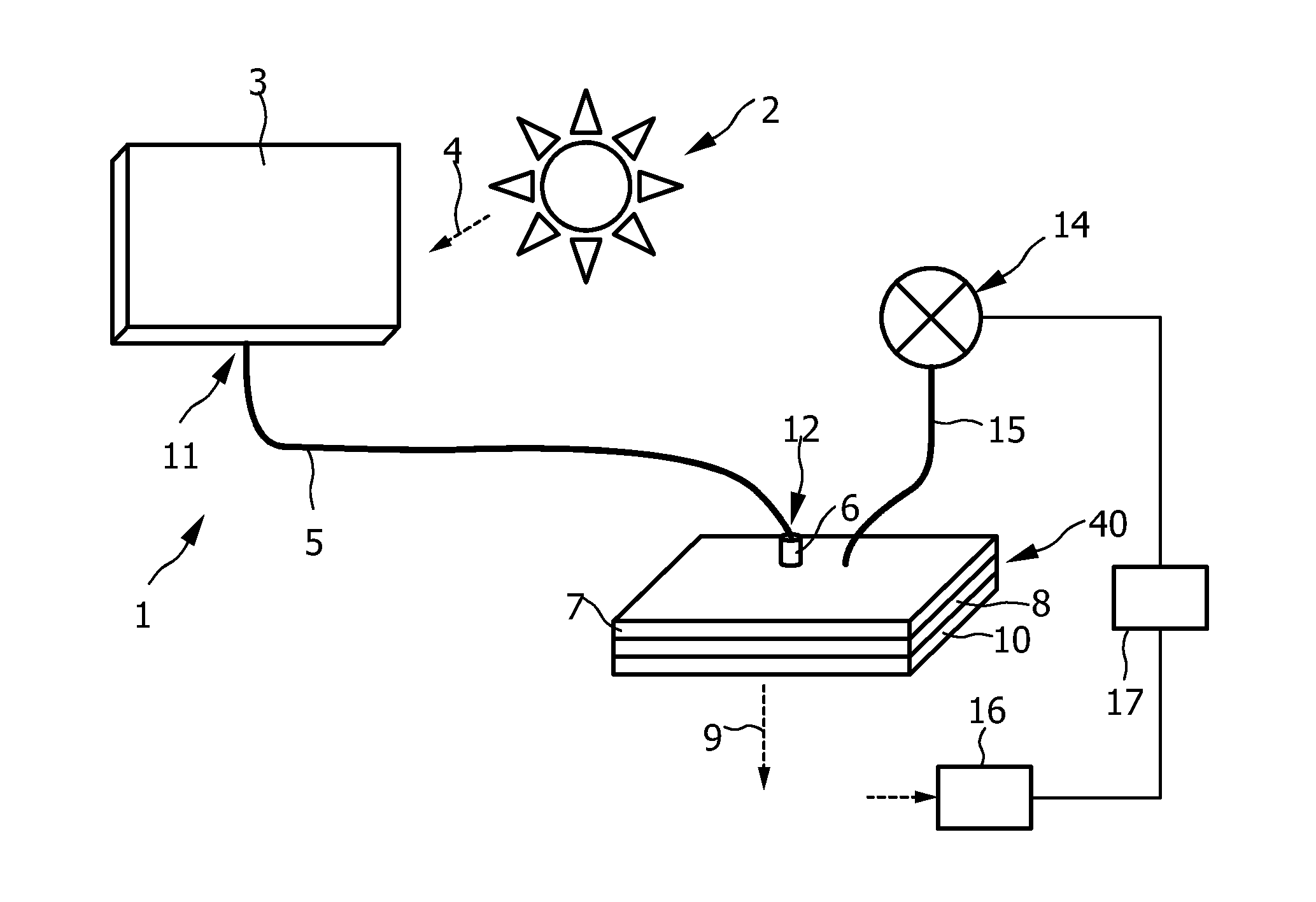
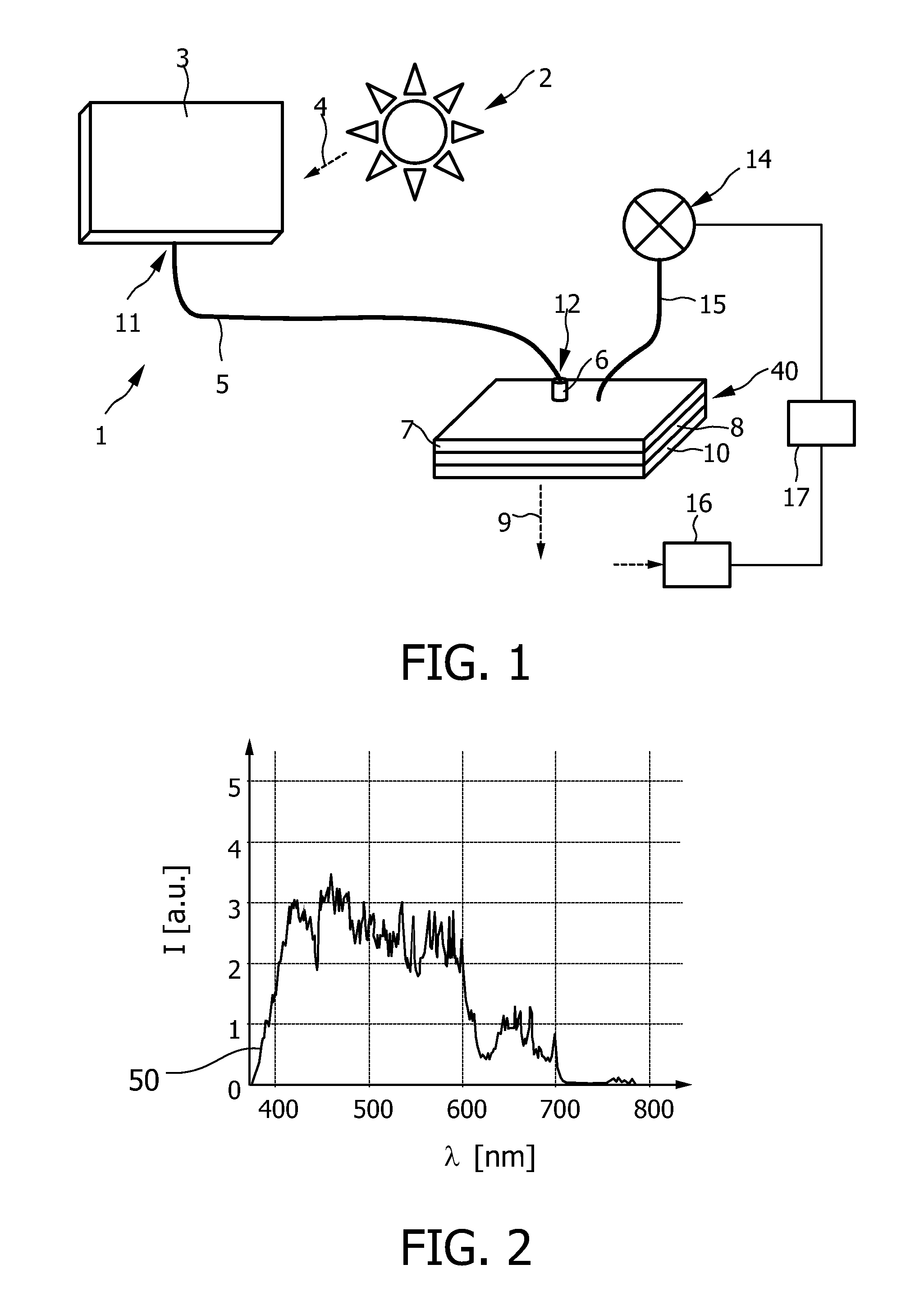
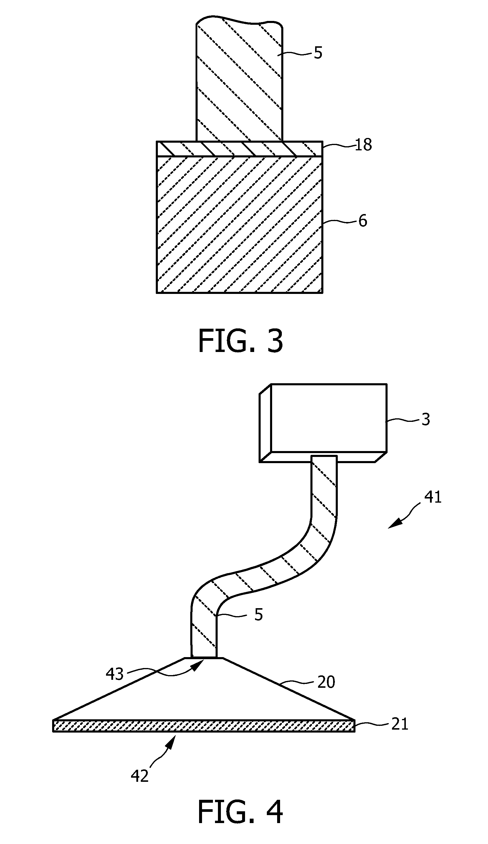
[0044]FIG. 1 shows schematically and exemplarily an embodiment of a daylight illumination apparatus. The daylight illumination apparatus 1 comprises a daylight collector 3 for collecting daylight 4 of the sun 2. The daylight illumination apparatus 1 further comprises a light guide 5 for guiding the daylight to an illumination location to be illuminated along an optical path. The illumination location is, for example, defined by a room within a building, which should be illuminated by daylight. While being guided by the light guide 5, the daylight is absorbed. The daylight illumination apparatus comprises photoluminescent material for emitting photoluminescent light for illuminating the illumination location. The photoluminescent material is arranged within the optical path such that the photoluminescent material can be illuminated by the guided daylight for generating the photoluminescent light. The photoluminescent material is adapted such that the photoluminescent light compensate...


PUM

PropertyMeasurementUnit
wavelengthsaaaaaaaaaa
photoluminescentaaaaaaaaaa
wavelengthaaaaaaaaaa

Abstract

The invention relates to a daylight illumination apparatus. A daylight collector (3) collects daylight (4), which is guided to an illumination location to be illuminated along an optical path by a light guide (5), wherein the daylight is absorbed by the light guide. A photoluminescent material (6, 8) is arranged within the optical path and emits photoluminescent light that compensates for the absorption of the daylight by the light guide. Absorption losses of the daylight can therefore effectively be compensated, without necessarily needing, for example, an active compensation light source. This allows providing compensated day-light illumination in a technically relatively simple way.

Description

FIELD OF THE INVENTION[0001]The invention relates to a daylight illumination apparatus and a daylight illumination method. The invention relates further to an object like a building comprising the daylight illumination apparatus.BACKGROUND OF THE INVENTION[0002]US 2006 / 0104081 A1 discloses a lighting system for a building having rooms. The lighting system includes a plurality of light collectors for collecting ambient light and a plurality of first light guides for conveying the light to a light accumulating vessel which has an internal reflective surface. A plurality of second light guides extend from the vessel to the rooms so that light which is collected and reflected in the vessel can be guided to the rooms for supplying the rooms with the light. The lighting system further comprises white light sources which are coupled to the vessel such that light of the white light sources can enter the vessel for compensating absorption losses of the daylight in the first light guides.[000...

Claims


Application Information

Patent Timeline
Patent Type & Authority Applications(United States)
IPC IPC(8): F21V9/02
CPCG02B6/0008F21V9/02F21Y2101/02F21S19/005F21V9/14F21S11/007F21Y2115/10F21V13/14F21V7/30F21V9/32
Inventor MEYER, JORGPEETERS, MARTINUS P. J.WEGH, RENE T.VAN GORKOM, RAMON P.HIKMET, RIFAT A. M.
Owner SIGNIFY HLDG BV
Why Eureka
Try Eureka