Method of potential routing, method of potential scheduling, and mesh node

a mesh node and routing technology, applied in the field of potential routing, can solve the problems of reducing achievable throughput and limiting the selection of inefficient paths, so as to prevent performance deterioration according to a network topology change, minimize packet transmission delay, and maximize network throughput

Inactive Publication Date: 2013-06-20
INST FOR BASIC SCI
View PDF8 Cites 20 Cited by
  • Summary
  • Abstract
  • Description
  • Claims
  • Application Information

AI Technical Summary

Benefits of technology

[0039]Further, when a network load is in a slight level through a dynamic parameter of a routing index that can adjust a geographical element and a traffic element, a routing path is set adjacent to geographical information-based routing, and when a network load is excessive, a routing path is set adjacent to back pressure routing. Thereby, delay of packet transmission is minimized, and network throughput is maximized.
[0040]Further, performance deterioration according to a network topology change is prevented through a multiple potential field for each destination, and a flexible path for each packet is provided.
[0041]Further, by scheduling based on a dynamic parameter, when a network load is in a slight level, a channel access priority is given to a packet that can go a farthest distance within a predetermined time period, and when a network load is in an excessive level, by determining a channel access order similarly to back pressure scheduling in consideration of only a traffic element, data are transmitted in a direction that can reduce a load of an entire network, and thus a network throughput can be more quickly optimized.

Problems solved by technology

Therefore, when a network traffic situation is dynamically changed, there is a limitation in selecting an inefficient path.
Thereby, when a network traffic situation is changed or when initial setting has an error, there is a scheduling problem that reduces achievable throughput.

Method used

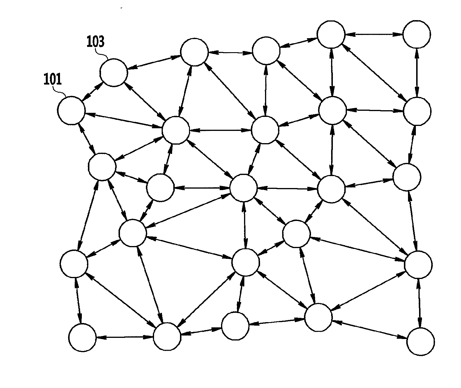
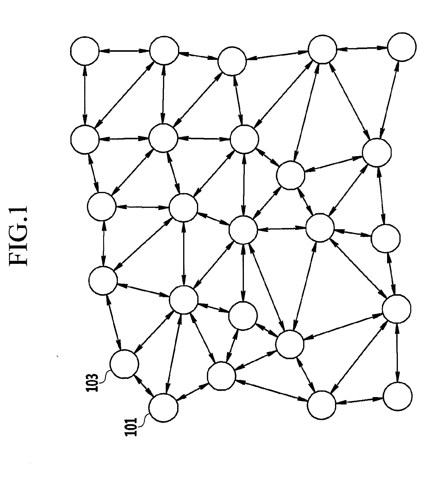
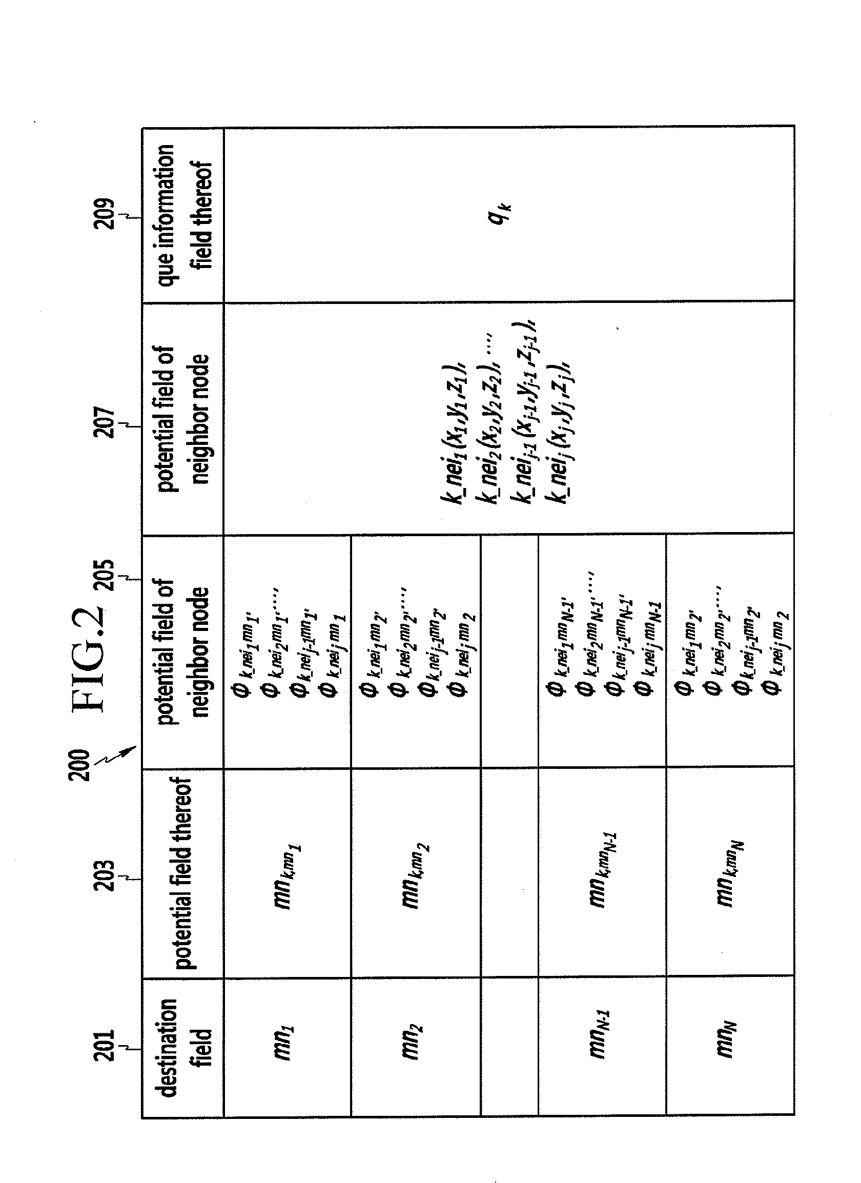

Image

  • Method of potential routing, method of potential scheduling, and mesh node
  • Method of potential routing, method of potential scheduling, and mesh node
  • Method of potential routing, method of potential scheduling, and mesh node

Examples


Embodiment Construction

[0051]In the following detailed description, only certain exemplary embodiments of the present invention have been shown and described, simply by way of illustration. As those skilled in the art would realize, the described embodiments may be modified in various different ways, all without departing from the spirit or scope of the present invention. Accordingly, the drawings and description are to be regarded as illustrative in nature and not restrictive. Like reference numerals designate like elements throughout the specification.

[0052]In the entire specification, unless explicitly described to the contrary, the word “comprise” and variations such as “comprises” or “comprising”, will be understood to imply the inclusion of stated elements but not the exclusion of any other elements.

[0053]In addition, the terms “-er”, “-or” and “module” described in the specification mean units for processing at least one function and operation and can be implemented by hardware components or softwa...


PUM


Abstract

A method of potential routing, a method of potential scheduling, and a mesh node are provided. Here, the mesh node includes a potential routing unit that transmits a data packet to a preset routing path by calculating a multiple potential, wherein the multiple potential indicates each potential of all destination nodes including a plurality of mesh nodes; and a potential scheduler that schedules a packet transmission order using the multiple potential.

Description

CROSS-REFERENCE TO RELATED APPLICATION[0001]This application claims priority to and the benefit of Korean Patent Application Nos. 10-2011-0138066 and 10-2012-0012503 filed in the Korean Intellectual Property Office on Dec. 20, 2011 and Feb. 7, 2012, the entire contents of which are incorporated herein by reference.BACKGROUND OF THE INVENTION[0002](a) Field of the Invention[0003]The present invention relates to a method of potential routing, a method of potential scheduling, and a mesh node.[0004](b) Description of the Related Art[0005]According to conventional potential routing technology, potential of a plurality of mesh nodes is calculated, and potential of a plurality of gateway nodes is set.[0006]Thereafter, when a data packet is transmitted at a specific node, potential and position information of one-hop neighbor nodes is requested and received, and a routing path is set according to the information. By transmitting a data packet to a single path or a multiple path according t...

Claims


Application Information

Patent Timeline
Patent Type & Authority Applications(United States)
IPC IPC(8): H04W72/04H04W84/18
CPCH04W40/18H04W40/20H04W72/12H04W84/18H04L45/12
Inventor JUNG, SANGSU
Owner INST FOR BASIC SCI
Why Eureka
Try Eureka