Manufacturing method of optical fiber ribbon, manufacturing device for optical fiber ribbon implementing said manufacturing method, and optical fiber ribbon manufactured with said manufacturing method

a manufacturing method and technology of optical fiber, applied in the direction of manufacturing tools, instruments, optical elements, etc., can solve the problems of inability to distinguish each of the optical fiber core cables, inability to use them as optical fiber cables, and inability to meet the needs of optical fiber core cables

Active Publication Date: 2013-06-20
THE FUJIKURA CABLE WORKS LTD +1
View PDF2 Cites 41 Cited by
  • Summary
  • Abstract
  • Description
  • Claims
  • Application Information

AI Technical Summary

Benefits of technology

[0032]In the optical fiber ribbon manufactured in the present invention, the plurality of optical fiber core cables are sent out in the parallel manner with the intervals provided therebetween, the uncured resin is applied to the plurality of optical fiber core cables, the plurality of interrupt members are moved, the interrupt members being arranged corresponding to the positions between each of the optical fiber core cables to interrupt the uncured resin, the positions at which the uncured resin is interrupted by the interrupt members and

Problems solved by technology

The above-described optical fiber ribbon 50 is difficult to be deformed in a width direction and warps greatly by being curled and folded; therefore, the configuration thereof is not suitable for being used as an optical fiber cable.
However, only 25 sheets of the optical fiber ribbons are required when using 8-core optical fiber core cables, and only 10 sheets of the optical fiber ribbons are needed when using 20-core optical fiber core cables.
However, regarding the optical fiber ribbons as such, distinguishability o

Method used


Image

  • Manufacturing method of optical fiber ribbon, manufacturing device for optical fiber ribbon implementing said manufacturing method, and optical fiber ribbon manufactured with said manufacturing method
  • Manufacturing method of optical fiber ribbon, manufacturing device for optical fiber ribbon implementing said manufacturing method, and optical fiber ribbon manufactured with said manufacturing method
  • Manufacturing method of optical fiber ribbon, manufacturing device for optical fiber ribbon implementing said manufacturing method, and optical fiber ribbon manufactured with said manufacturing method

Examples


first embodiment

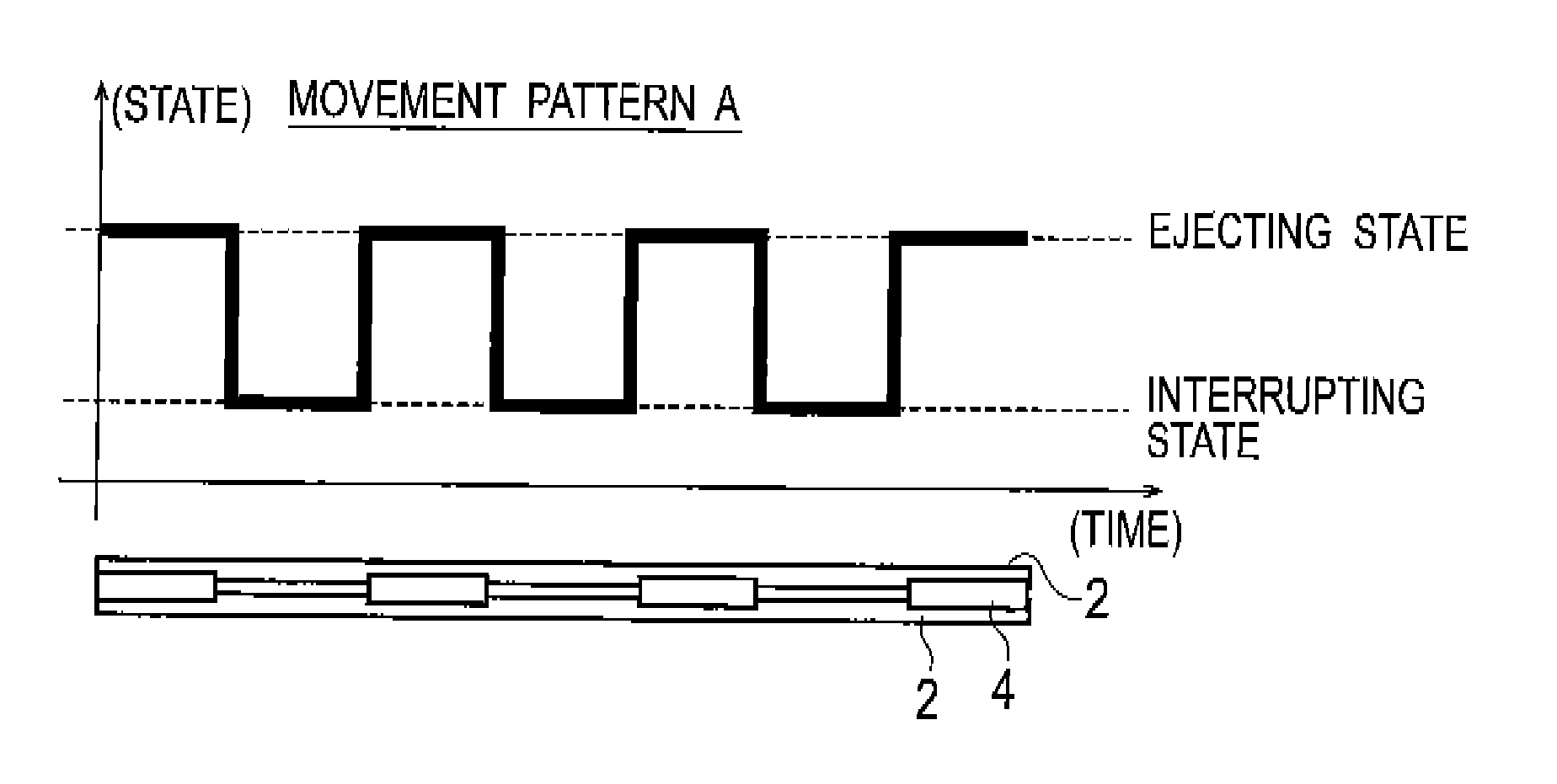
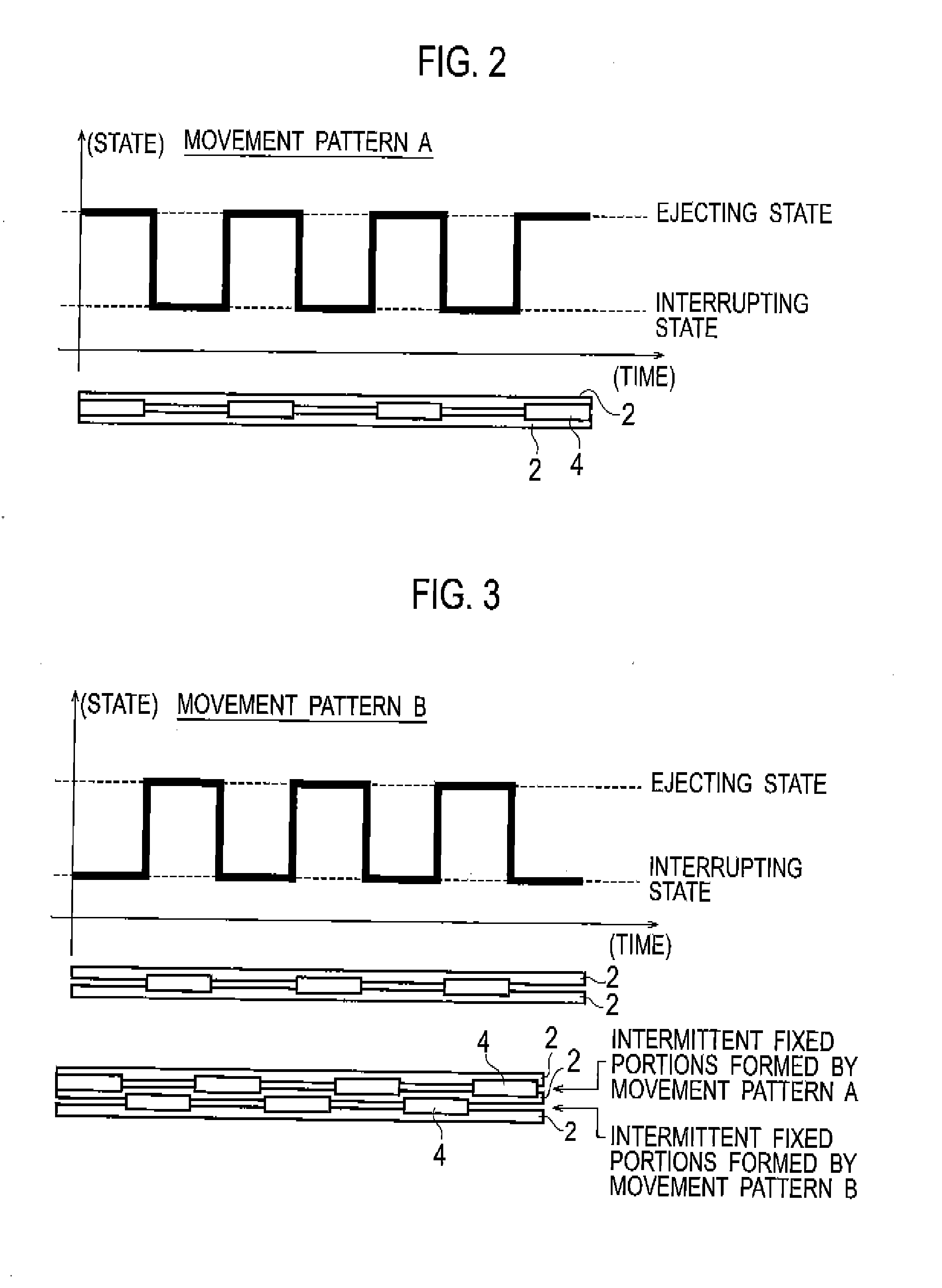
[0050]In a manufacturing method for an optical fiber ribbon concerned, subunits are configured by arranging a plurality of optical fiber core cables in parallel and partially coupling the neighboring optical fiber core cables with each other at given intervals in a longitudinal direction. Moreover, the plurality of subunits arranged in parallel are partially coupled with each other by coupling together the optical fiber core cables positioned at side edges of the respective subunits at given intervals in the longitudinal direction, thereby manufacturing the optical fiber ribbon.

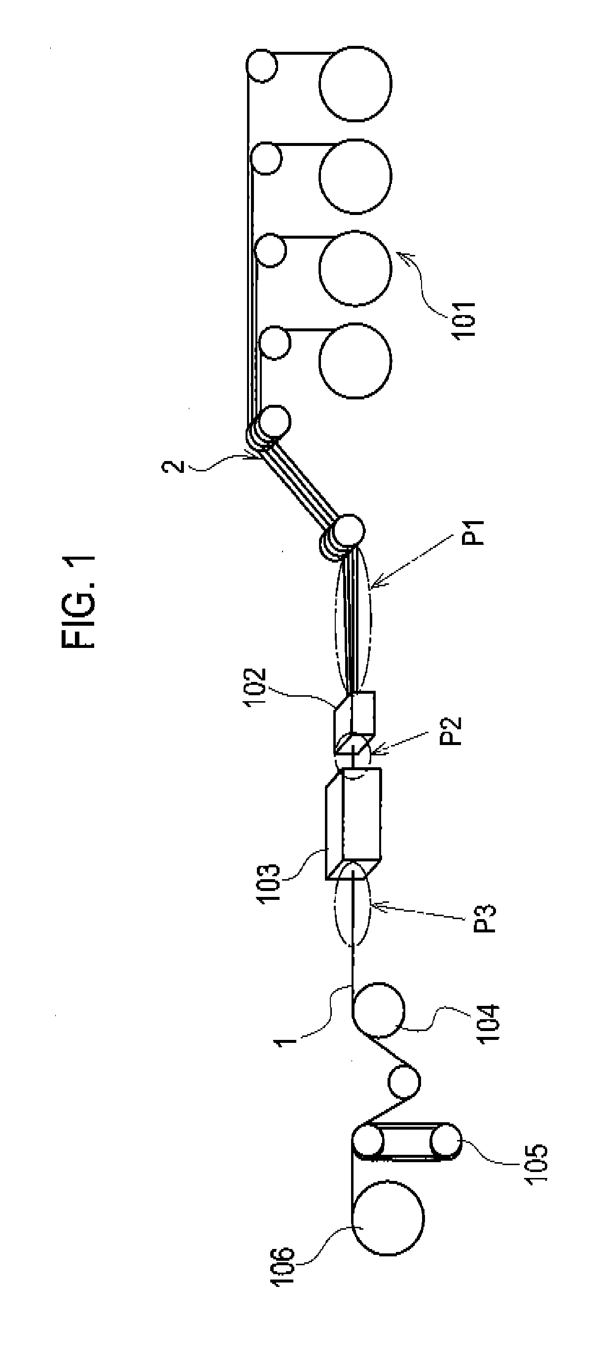
[0051]FIG. 1 is a perspective view showing manufacturing processes of the manufacturing method for the optical fiber ribbon according to a first embodiment of the present invention.

[0052]Specifically, a plurality of optical fiber core cables 2 are sent out from a plurality of optical fiber core cable sending-out devices 101 and sent to an intermittent resin-coating device 102. The respective optical fiber cor...

second embodiment

[0068]In this embodiment, distinguishability between the subunits in an optical fiber ribbon is improved by making repeated periods and phases different for respective moving patterns of the interrupt members.

[0069]FIG. 6 is a graph showing the moving patterns of the interrupt members according to the second embodiment.

[0070]In this embodiment, as shown in FIG. 6, the optical fiber ribbon is manufactured by using movement patterns C to F of which respective periods and phases have a constant relationship with each other. The coupled portions 4 within each subunit are formed by using the movement patterns C, D and E having the same period but different phases. The coupled portions 5 coupling the subunits with each other are formed by using the movement pattern F having a different period from that of the coupled portions 4 within each subunit.

[0071]FIG. 7 is a plan view showing a configuration of the optical fiber ribbon according to the second embodiment.

[0072]As shown in FIG. 7, th...

third embodiment

[0074]FIG. 8 is a graph showing moving patterns of the interrupt members according to a third embodiment.

[0075]In a case of reducing the number of coupled portions present in the same position in the width direction of an optical fiber ribbon, phases can be made different as shown in FIG. 8 for moving patterns of the interrupt members for forming the coupled portions between the subunits. In this case, two types of patterns, F and G, are used for the movement patterns for forming the coupled portions between the subunits.

[0076]FIG. 9 is a plan view showing a configuration of the optical fiber ribbon according to the third embodiment.

[0077]As shown in FIG. 3, the optical fiber ribbon is manufactured by using two types of patterns, F and G, for the movement patterns for forming the coupled portions 5 between the subunits.

[0078]Moreover, when the period of the movement patterns for forming the coupled portions 4 within each subunit is set to integral multiple of that of the movement pa...


PUM

PropertyMeasurementUnit
Phaseaaaaaaaaaa

Abstract

A manufacturing method for an optical fiber ribbon, in which: a plurality of optical fibers are arranged in parallel and the neighboring optical fibers are partially coupled with each other at given intervals in a longitudinal direction to form a subunit; and the optical fibers positioned at side edges of the neighboring subunits are partially coupled with each other at a given intervals in the longitudinal direction, includes: sending out the optical fibers in a parallel manner with intervals provided therebetween, applying an uncured resin to the optical fibers, continuously changing positions at which the uncured resin is interrupted by a plurality of interrupt members, and forming coupled portions at which the optical fibers are coupled to each other by irradiating resin curing energy, wherein a moving period or phase of the interrupt members is changed for every arbitrary optical fibers.

Description

CROSS-REFERENCE TO RELATED APPLICATIONS[0001]The application is a Continuation of PCT Application No. PCT / JP2011 / 068427, filed on Aug. 12, 2011, and claims the benefit of priority from the prior Japanese Patent Application No. 2010-184307, filed on Aug. 19, 2010, the entire contents of which are incorporated herein by reference.BACKGROUND OF THE INVENTION[0002]The present invention relates to a manufacturing method of an optical fiber ribbon in which a plurality of optical fiber core cables are arranged in parallel and coupled, a manufacturing device for an optical fiber ribbon implementing the manufacturing method and an optical fiber ribbon manufactured with the manufacturing method.[0003]Conventionally, an optical fiber ribbon as shown in FIG. 14 has been proposed, in which a plurality of subunits 53, each of which are formed by covering a plurality of optical fiber core cables 51 with a covering portion 52 in an entire length in a longitudinal direction, are assembled. The plura...

Claims


Application Information

Patent Timeline
IPC IPC(8): G02B6/44
CPCG02B6/4404G02B6/448G02B6/4403G02B6/4405
Inventor MATSUZAWA, TAKASHITAKE, YUKIKOOSATO, KENOKADA, NAOKIYAMADA, YUSUKE
Owner THE FUJIKURA CABLE WORKS LTD
Why Eureka
Try Eureka