
Vacuum cleaner

a vacuum cleaner and vacuum cleaner technology, applied in the field of vacuum cleaners, can solve the problems of significant increase in the overall size achieve the effects of improving the sealing of the filter, reducing the height of the vacuum cleaner, and improving the accessibility of the filter

Active Publication Date: 2013-06-27
DYSON TECH LTD
View PDF11 Cites 82 Cited by
  • Summary
  • Abstract
  • Description
  • Claims
  • Application Information

AI Technical Summary

Benefits of technology

The invention is about a vacuum cleaner with a separating apparatus that includes a filter. The filter is designed in a way that air flow enters the filter in a radial direction, which makes the housing of the filter more compact and beneficial for handheld vacuum cleaners. The vacuum cleaner also includes a second cyclonic cleaning stage located downstream of the first cyclonic cleaning stage, which reduces the height of the separating apparatus. This design helps to make the vacuum cleaner more compact and lightweight.

Problems solved by technology

Although this configuration permits a relatively large filter to be used, the overall size of the vacuum cleaner is increased significantly.

Method used


Image

  • Vacuum cleaner
  • Vacuum cleaner
  • Vacuum cleaner

Examples


Embodiment Construction

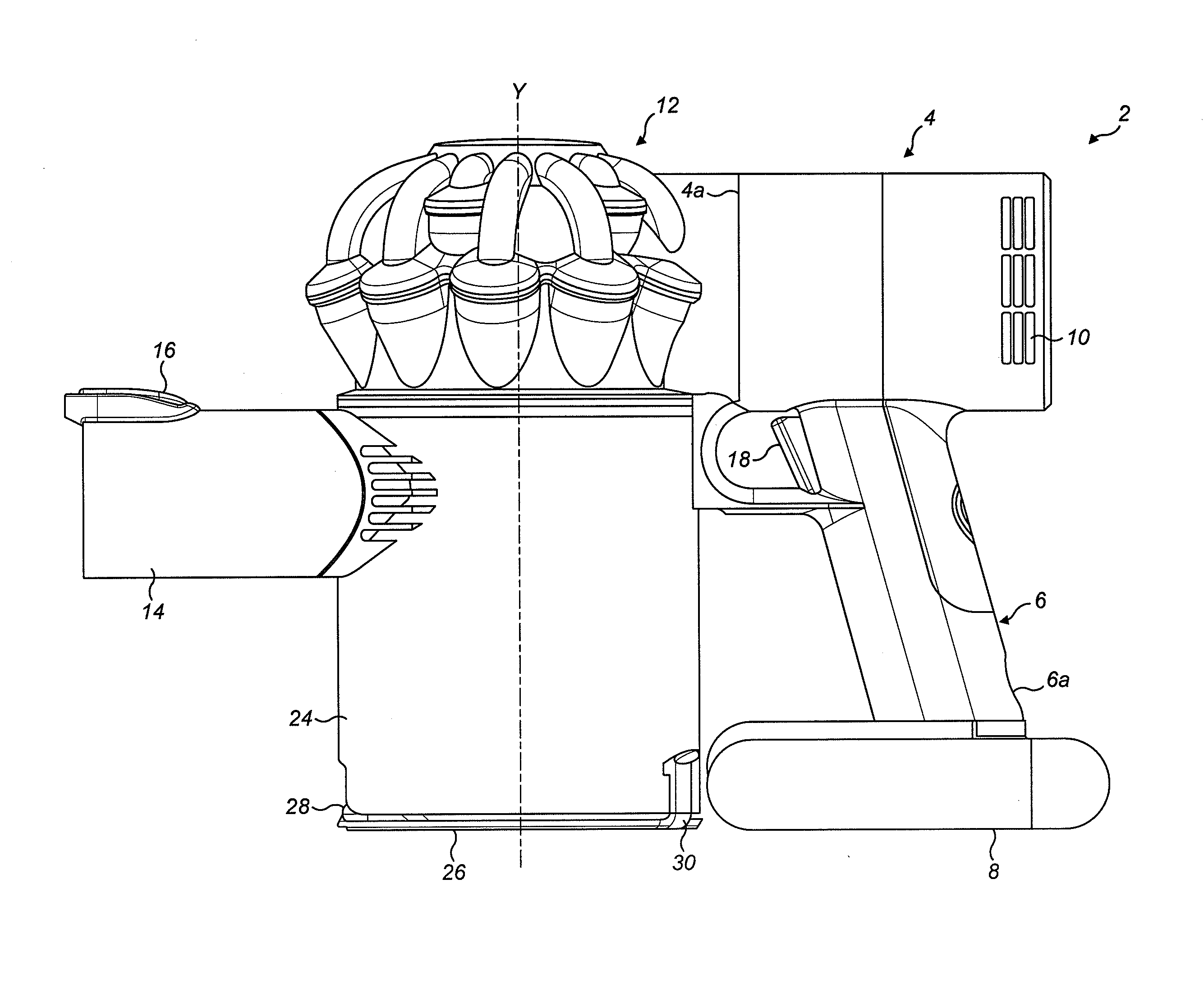
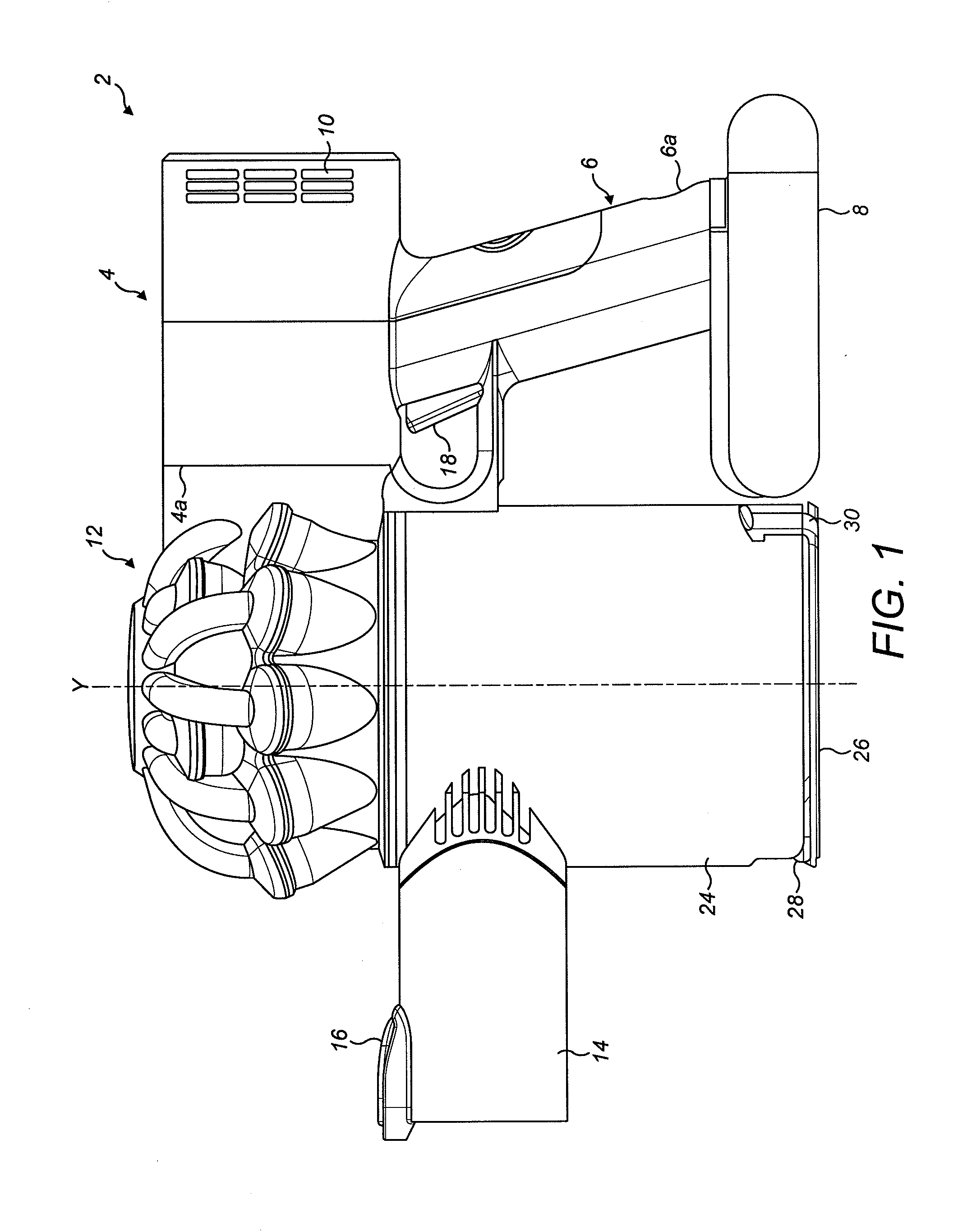
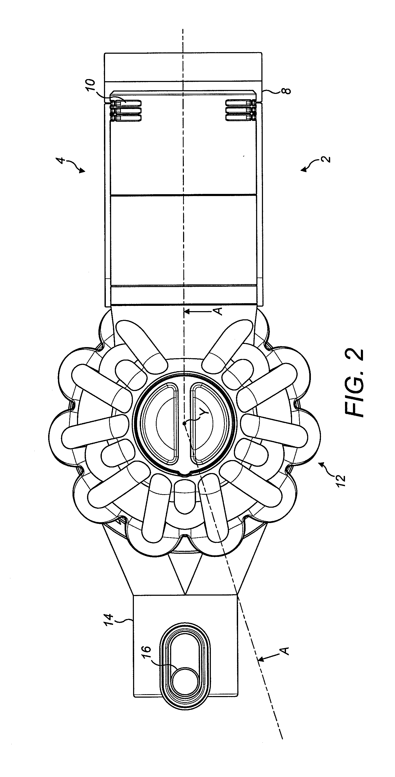
[0024]Referring firstly to FIGS. 1 and 2, a handheld vacuum cleaner 2 has a main body 4 which houses a motor and fan unit (not shown) above a generally upright handle or grip portion 6. The lower end 6a of the handle 6 supports a generally slab-like battery pack 8. A set of exhaust vents 10 are provided on the main body 4 for exhausting air from the handheld vacuum cleaner 2.

[0025]The main body 4 supports a cyclonic separating apparatus 12 that functions to remove dirt, dust and other debris from a dirt-bearing airflow drawn into the vacuum cleaner by the motor and fan unit. The cyclonic separator 12 is attached to a forward part 4a of the main body 4 and an air inlet nozzle 14 extends from a forward portion of the cyclonic separator that is remote from the main body 4. The air inlet nozzle 14 is configured so that a suitable brush tool can be removably mounted to it and includes a catch 16 for securely holding such a brush tool when the tool is engaged with the inlet. The brush too...


PUM

PropertyMeasurementUnit
Flow rateaaaaaaaaaa
Circumferenceaaaaaaaaaa

Abstract

A vacuum cleaner comprising a cyclonic separating apparatus including a dirty air inlet, a main body connected to the cyclonic separating apparatus and a motor and fan unit for generating an airflow through the cyclonic separating apparatus from the dirty air inlet to a clean air outlet, wherein the cyclonic separating apparatus includes at least a first cyclonic cleaning stage and an elongate filter arranged fluidly downstream from the first cyclonic cleaning stage, the elongate filter being housed in a duct at least partially surrounded by the first cleaning stage, and wherein the filter comprises an inlet portion and a filter portion defining a generally tubular filter chamber, the inlet portion including one or more radially facing inlets to permit air to flow into the inlet portion in a radial direction from where the air flows from the inlet portion to the filter chamber in an axial direction.

Description

REFERENCE TO RELATED APPLICATIONS[0001]This application claims the priority of United Kingdom Application No. 1122162.9, filed Dec. 22, 2011, the entire contents of which are incorporated herein by reference.FIELD OF THE INVENTION[0002]The invention relates to a vacuum cleaner, particularly of the handheld type of vacuum cleaner being generally compact and lightweight. The invention also relates to a filter for such a vacuum cleaner.BACKGROUND OF THE INVENTION[0003]Handheld vacuum cleaners are popular with users due to their light weight and inherent portability, as well as the lack of power cords, which makes such vacuum cleaners particularly convenient for spot cleaning tasks as well as for cleaning larger areas. The cleaning efficiency of handheld vacuum cleaners is improving and it is known to equip a handheld vacuum cleaner with a cyclonic separating apparatus to separate the dirt and dust from the incoming flow of dirt laden air. One such example is disclosed in EP2040599B, wh...

Claims


Application Information

Patent Timeline
IPC IPC(8): A47L9/16
CPCA47L9/165A47L9/127A47L9/1666A47L9/1641A47L9/1658A47L9/1633A47L9/16B04C5/185B04C5/28A47L5/24A47L9/12A47L9/1608A47L9/1616A47L5/06A47L9/1683A47L9/322
Inventor PEACE, MICHAEL JAMES
Owner DYSON TECH LTD
Features
  • Generate Ideas
  • Intellectual Property
  • Life Sciences
  • Materials
  • Tech Scout
  • Unparalleled Data Quality
  • Higher Quality Content
  • 60% Fewer Hallucinations
Learn More