Medium conveyance apparatus and image forming apparatus

a technology of image forming apparatus and conveyancing apparatus, which is applied in the direction of thin material handling, instruments, article separation, etc., to achieve the effect of suppressing deviations in positional relationship between respective parts of the apparatus and improving conveyancing performan

Inactive Publication Date: 2013-06-27
OKI DATA CORP
View PDF14 Cites 10 Cited by
  • Summary
  • Abstract
  • Description
  • Claims
  • Application Information

AI Technical Summary

Benefits of technology

[0008]According to the medium mounting unit of the invention, conveyance performance is improved because deviation of positional relationship amo

Problems solved by technology

With such an apparatus, it is not easy to render medium conveyance stable for a long time at a time that

Method used


Image

  • Medium conveyance apparatus and image forming apparatus
  • Medium conveyance apparatus and image forming apparatus
  • Medium conveyance apparatus and image forming apparatus

Examples


first embodiment

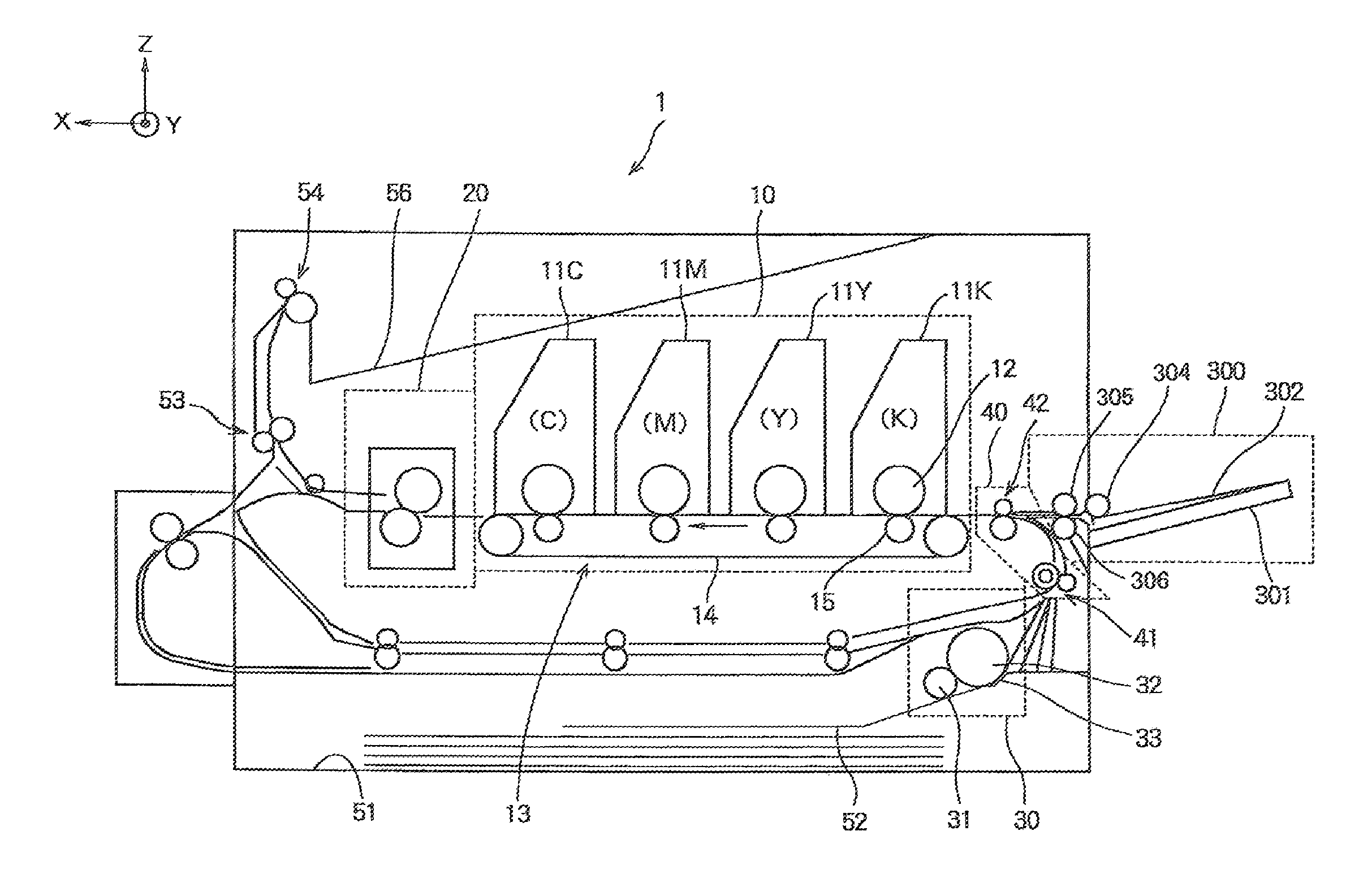
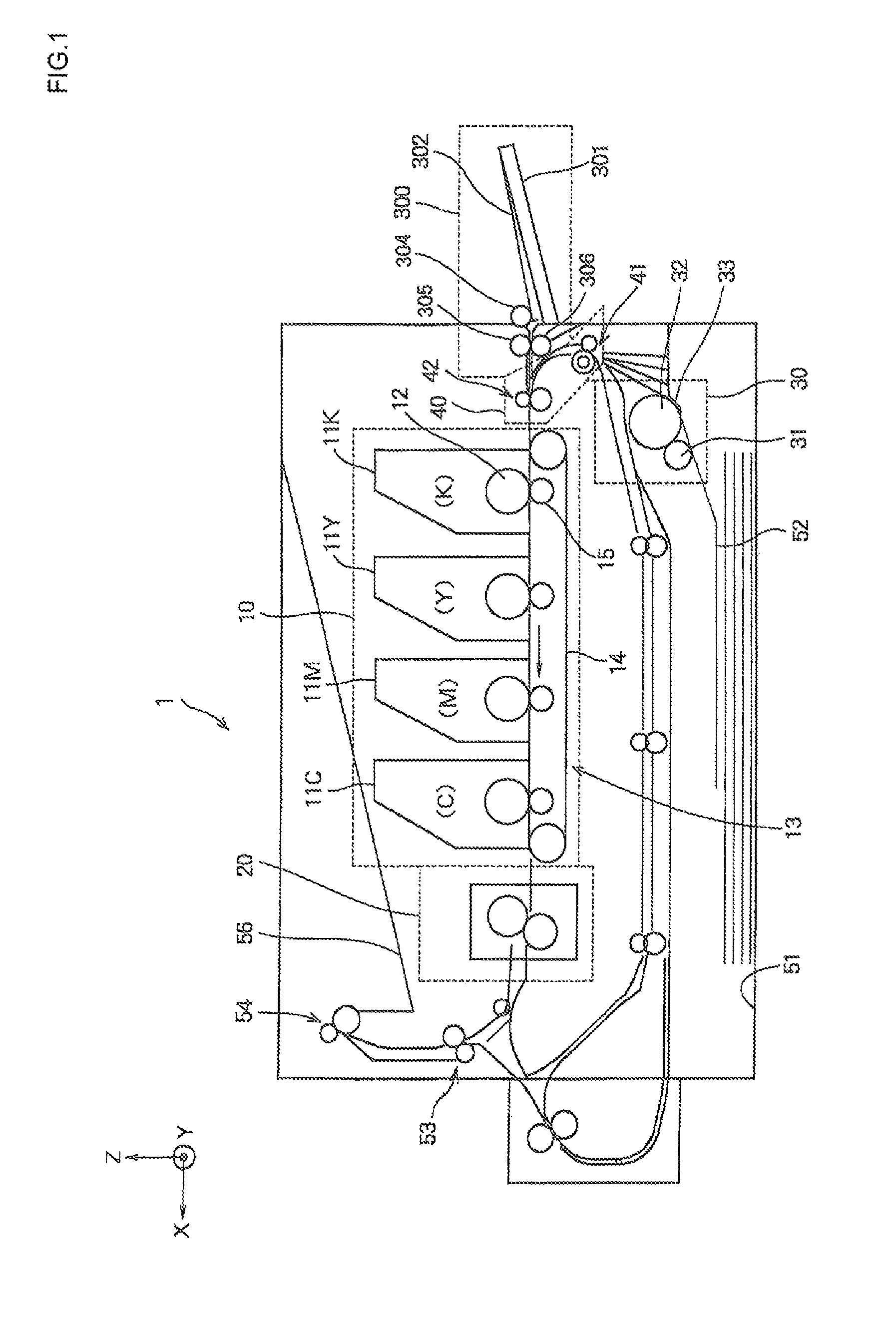
[0025]FIG. 1 is a schematic structural view, when seen from their front, of essential portions of an image forming apparatus according to the first embodiment in which a medium mounting unit according to this invention applies.

[0026]In FIG. 1, a paper tray 51 stacking recording paper 52 inside is disposed at an inside lower part of an image forming apparatus 1 having a structure as an electrophotographic printer, and a paper feeding unit 30 for feeding the recording paper 52 as a medium sheet by sheet is arranged on a paper feeding side of the paper tray 51. The paper feeding unit 30 is formed with a pickup roller 31 arranged to press the recording paper 52 lifted up to a certain level, a feed roller separating sheet by sheet the recording paper 52 fed by the pickup roller 31, and a separation piece 33.

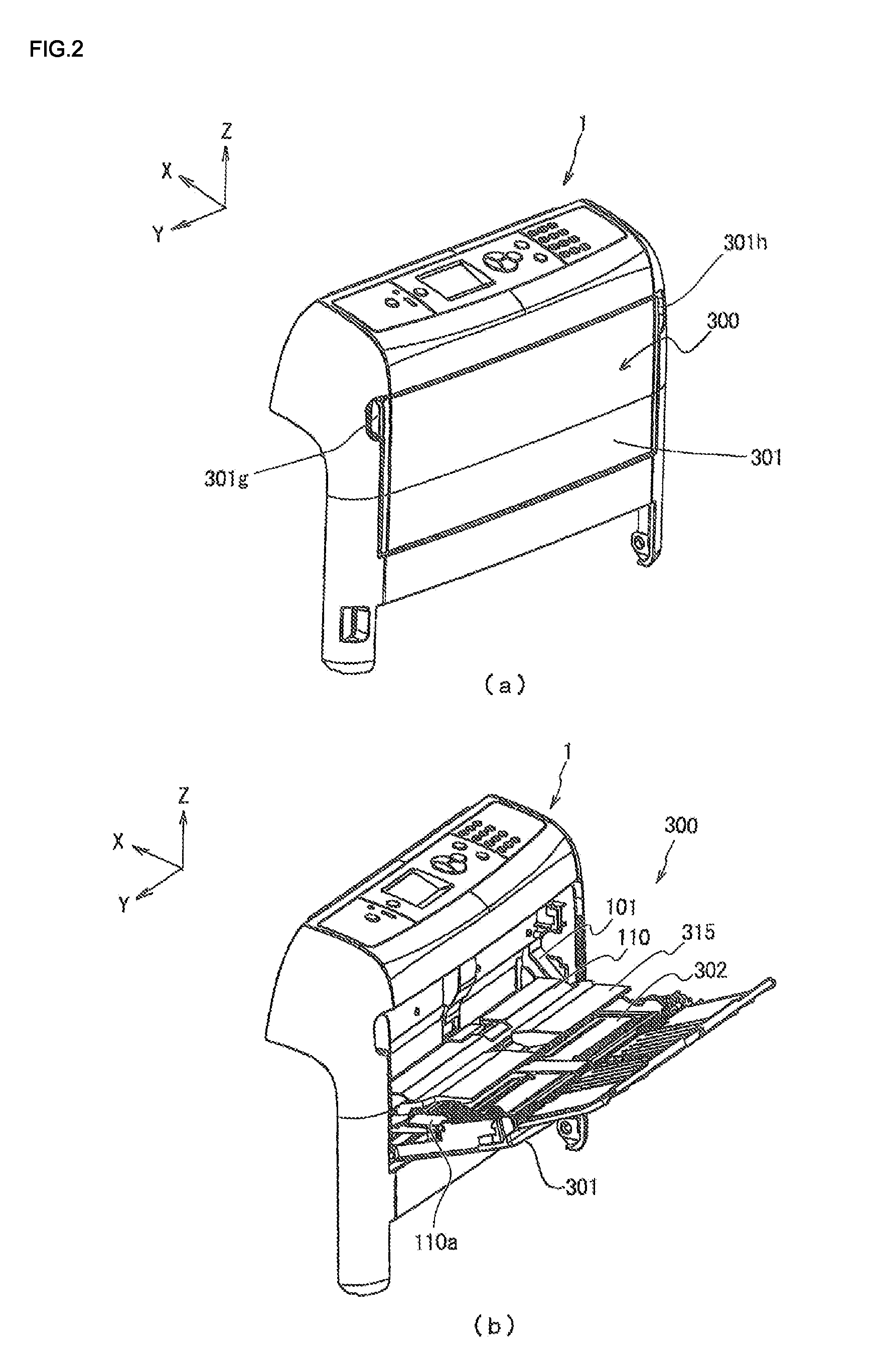
[0027]A manual feed tray 300 is formed with a paper mounting plate 302 mounting recording paper 370 (see, FIG. 10), a manual feed tray cover 301 rotationally holding the paper mountin...

second embodiment

[0067]FIG. 12 is an assembly illustration for describing an assembling relation between an apparatus frame 201 and a manual feed tray cover 301 in a medium conveyance apparatus according to a second embodiment, showing a state that the apparatus frame 201 and the manual feed tray cover 301 having a paper mounting plate 302 are separated from each other; FIG. 13(a) is a structural view showing essential structures of the medium conveyance apparatus in which the manual feed tray cover 301 is in the closed position; FIG. 13(b) is a partly enlarged view of a circled portion 151 drawn by a single dot chain line in FIG. 13(a).

[0068]Mainly different points between the image forming apparatus using the apparatus frame 201 and the image forming apparatus according to the first embodiment shown in FIG. 1 described above are in that the apparatus frame 201 is added with stopper members 201c, 201d. Accordingly, the same reference numbers are provided to portions of the image forming apparatus u...


PUM


Abstract

A medium conveyance apparatus used in an image forming apparatus, includes a medium mounting unit held at a body or apparatus frame for mounting a medium, a conveying member supported rotationally around an axis to the body for conveying the medium, and a separating member being held at the body and contacting with the conveying member. The medium mounting unit includes an engaging portion for engaging the body, whereas the body or apparatus frame includes an engaged portion to be engaged with the engaging portion, and the engaging portion includes a contacting portion for regulating the body or apparatus frame in a conveyance direction of the medium. This medium conveyance apparatus maintains improved medium conveyance capability for a long period.

Description

CROSS REFERENCE TO RELATED APPLICATION[0001]This application claims priority benefits under 35 USC, section 119 on the basis of Japanese Patent Application No. 2011-279369, the disclosure of which is incorporated herein by reference.BACKGROUND OF THE INVENTION[0002]1. Field of the Invention[0003]This invention relates to a medium conveyance apparatus for manual feeding tray of an image forming apparatus.[0004]2. Description of Related Art[0005]In conventional medium conveyance apparatuses and image forming apparatuses, a medium mounting unit is attached to an apparatus body. Japanese Patent Application Publication No. 2010-228832 discloses such a medium mounting unit (particularly, 6 page, FIG. 1).[0006]With such an apparatus, it is not easy to render medium conveyance stable for a long time at a time that media are fed out of the medium mounting unit, so that improvements in conveyance performance are in need.SUMMARY OF THE INVENTION[0007]A medium conveyance apparatus according to ...

Claims


Application Information

Patent Timeline
IPC IPC(8): B65H1/00B65H3/06
CPCB65H1/04B65H3/0684B65H3/5261B65H2402/441B65H2403/732B65H2405/11164G03G15/6514B65H2407/21B65H2601/523B65H1/00B65H3/06B65H3/44B65H2405/324
Inventor MATSUMOTO, KEIGO
Owner OKI DATA CORP
Why Eureka
Try Eureka