Liquid container, liquid container unit, and liquid ejecting apparatus

a liquid container and liquid ejecting technology, which is applied in the direction of printing, power drive mechanisms, printing mechanisms, etc., can solve the problem of not being easy to inject ink from the injection port, and achieve the effect of easy liquid injection

Inactive Publication Date: 2013-07-04
SEIKO EPSON CORP
View PDF37 Cites 103 Cited by
  • Summary
  • Abstract
  • Description
  • Claims
  • Application Information

AI Technical Summary

Benefits of technology

[0009]Having been contrived in order to resolve the foregoing problems, the present invention has the primary objective of providing a liquid container, liquid container unit, and liquid ejecting apparatus whereby a liquid can be easily made to flow into a liquid containing portion from an injection port.
[0066]According to this configuration, a liquid ejecting apparatus whereby the injection ports can be displaced to a position at which the task of injecting the liquid is easy can be achieved, because the liquid container unit whereby the injection ports for the liquid can be displaced is provided.

Problems solved by technology

However, in the case of the configuration of such description, because the injection port will be positioned on the inside of the apparatus chassis, it has not been easy to inject the ink from the injection port.

Method used


Image

  • Liquid container, liquid container unit, and liquid ejecting apparatus
  • Liquid container, liquid container unit, and liquid ejecting apparatus
  • Liquid container, liquid container unit, and liquid ejecting apparatus

Examples


first embodiment

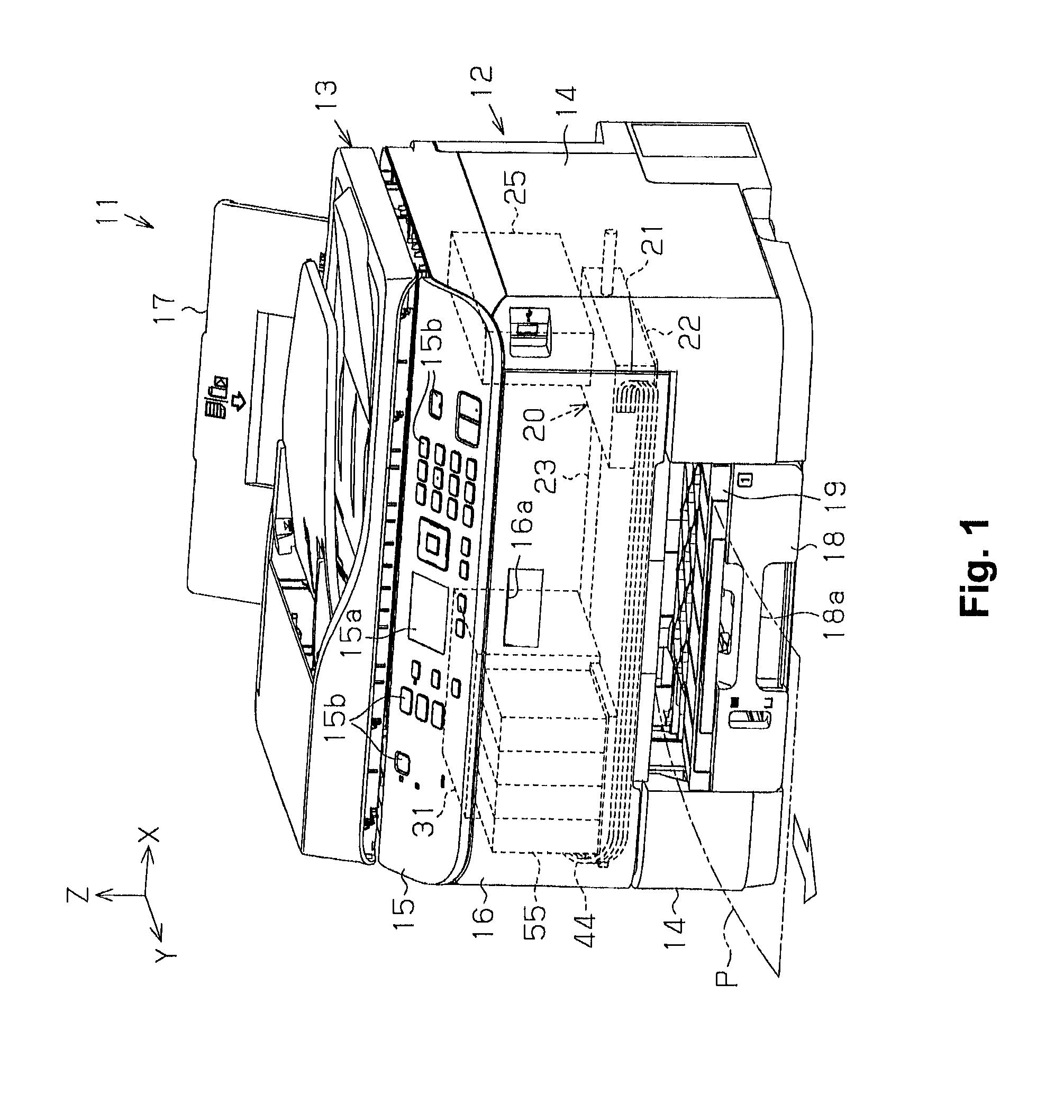
[0088]As illustrating in FIG. 1, a printer 11 is constituted of an apparatus body 12, and a scanner unit 13 serving as an image read device installed on the apparatus body 12 by being connected thereto on the side opposite to the direction of gravity (the upward side) in the vertical direction Z. The apparatus body 12 is constituted of an apparatus case 14, which is one example of a chassis, of the printer 11, which is constituted of a plurality of members; a liquid ejection unit 20 for ejecting ink onto a sheet of paper P is provided within a spatial region enclosed by the apparatus case 14.

[0089]Arranged on the apparatus case 14 is an operation panel 15 which is operated by a user when the printer 11 is being manipulated, on an upper side in the front direction, which serves as a discharge direction Y for a sheet of paper P that is printed. The operation panel 15 is provided with a display unit (for example, a liquid crystal display) 15a for displaying a menu screen and the like, ...

second embodiment

[0139]The liquid container unit of the second embodiment shall be described next. In the description of the second embodiment, those constituent elements which are identical to those of the printer 11 in the first embodiment have been assigned identical reference numerals, and a description thereof shall be omitted as appropriate.

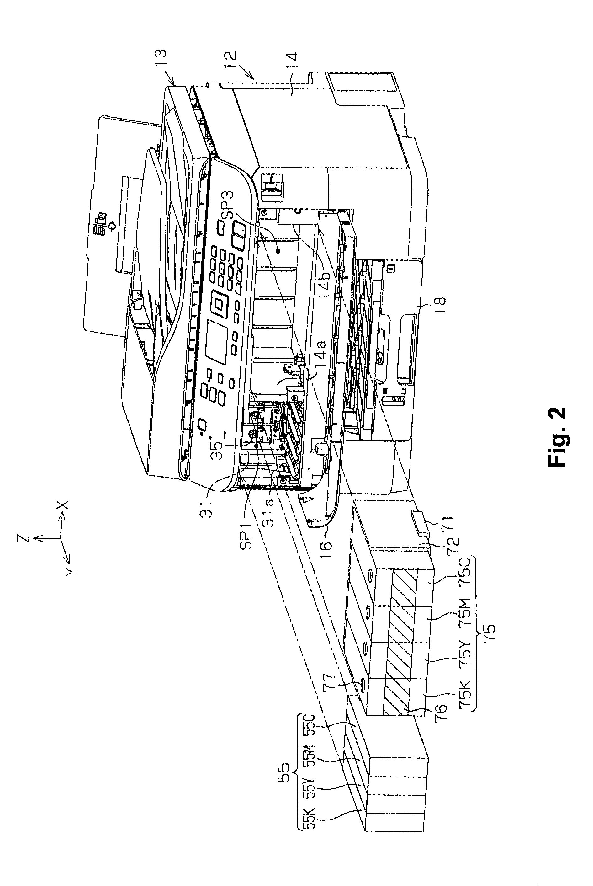
[0140]As illustrated in FIG. 10, a tank unit 70, which is one example of the liquid container unit, is provided with the ink tanks 75 having the injection ports 77 for ink, which are one example of the liquid containers, as well as with a tank case 79, which is one example of a container holder, for holding the ink tanks 75. The tank case 79 has a substantially boxed shape, which opens in one direction; insertion of the ink tanks 75 from the opening thereof makes it possible to hold the ink tanks 75 in the interior in a state where the injection ports 77 are not exposed. The tank unit 70 supplies the ink to the printer 11 from the ink tanks 75 via the conne...

third embodiment

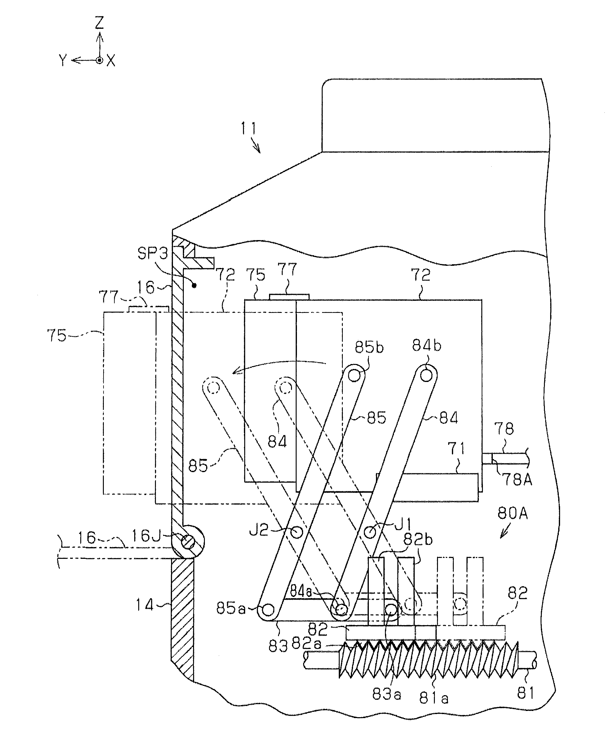
[0175]The liquid container of the third embodiment shall be described next. In the description of the third embodiment, those constituent elements which are identical to those of the printer 11 in the first embodiment and the tank unit 70 of the second embodiment have been assigned identical reference numerals, and a description thereof shall be omitted as appropriate.

[0176]The present embodiment is the ink tanks 75, to which are provided: the injection port 77 for ink; the ink chamber 75S, which is a liquid containing portion, capable of containing the ink that is injected from the injection ports 77; and the supply port 78A, which can be connected to the liquid supply member capable of communication to the liquid ejection head of the printer 11, wherein the ink tanks have a displacement structure whereby the first portion comprising the injection ports 77 in the ink tanks 75 can be displaced in a relative manner with respect to a second portion which is different than the first po...


PUM


Abstract

A liquid container capable of communicating to a liquid ejection head of a liquid ejecting apparatus via a liquid supply member is provided with an injection port for a liquid, a liquid containing portion capable of containing the liquid injected from the injection port, and a supply port capable of connecting to the liquid supply member. A first portion of the liquid container including the injection port is displaceable in a relative manner with respect to a second portion of the liquid container which is different than the first portion and includes the liquid containing portion.

Description

CROSS-REFERENCE TO RELATED APPLICATIONS[0001]The present application claims the priority of Japanese Patent Application No. 2011-269296, filed on 8 Dec. 2011, the entirety of which is incorporated herein by reference.BACKGROUND[0002]1. Technical Field[0003]The present invention relates to a liquid container for containing a liquid to be supplied to a liquid ejection head for ejecting the liquid, a liquid container unit for holding the liquid container, and a liquid ejecting apparatus provided with a liquid ejection head for ejecting a liquid.[0004]2. Related Art[0005]A liquid ejecting apparatus for ejecting ink, which is one example of a liquid, from, for example, a liquid ejection head onto a sheet of paper, which is one example of a medium, to print an image, including text or graphics, has been conventionally put to practical use. This type of apparatus supplies the ink to the liquid ejecting head for ejecting the ink, from an ink cartridge (a liquid container) containing the ink...

Claims


Application Information

Patent Timeline
Patent Type & Authority Applications(United States)
IPC IPC(8): B41J2/175
CPCB41J2/175B41J2/17553B41J2/1752B41J2/17509B41J2/01B41J25/24B41J2/17506B41J2/17513B41J2/17526
Inventor NAKAMURA, KOTAROOYA, SHUN
Owner SEIKO EPSON CORP
Why Eureka
Try Eureka