Color wheel with fan blade

a technology of fan blades and color wheels, which is applied in the direction of instruments, projectors, optics, etc., can solve the problems of halogen lamps, short life, and high heat generation

Inactive Publication Date: 2013-07-04
HON HAI PRECISION IND CO LTD
View PDF5 Cites 87 Cited by
  • Summary
  • Abstract
  • Description
  • Claims
  • Application Information

AI Technical Summary

Problems solved by technology

Light sources of current projectors, such as high-pressure mercury-vapor lamp, tungsten-halogen lamps, and metal-halogen lamps, are known to consume high power, with a short lifetime, as well the

Method used


Image

  • Color wheel with fan blade
  • Color wheel with fan blade
  • Color wheel with fan blade

Examples


Embodiment Construction

[0010]The present disclosure will be described with references to the accompanying diagrams.

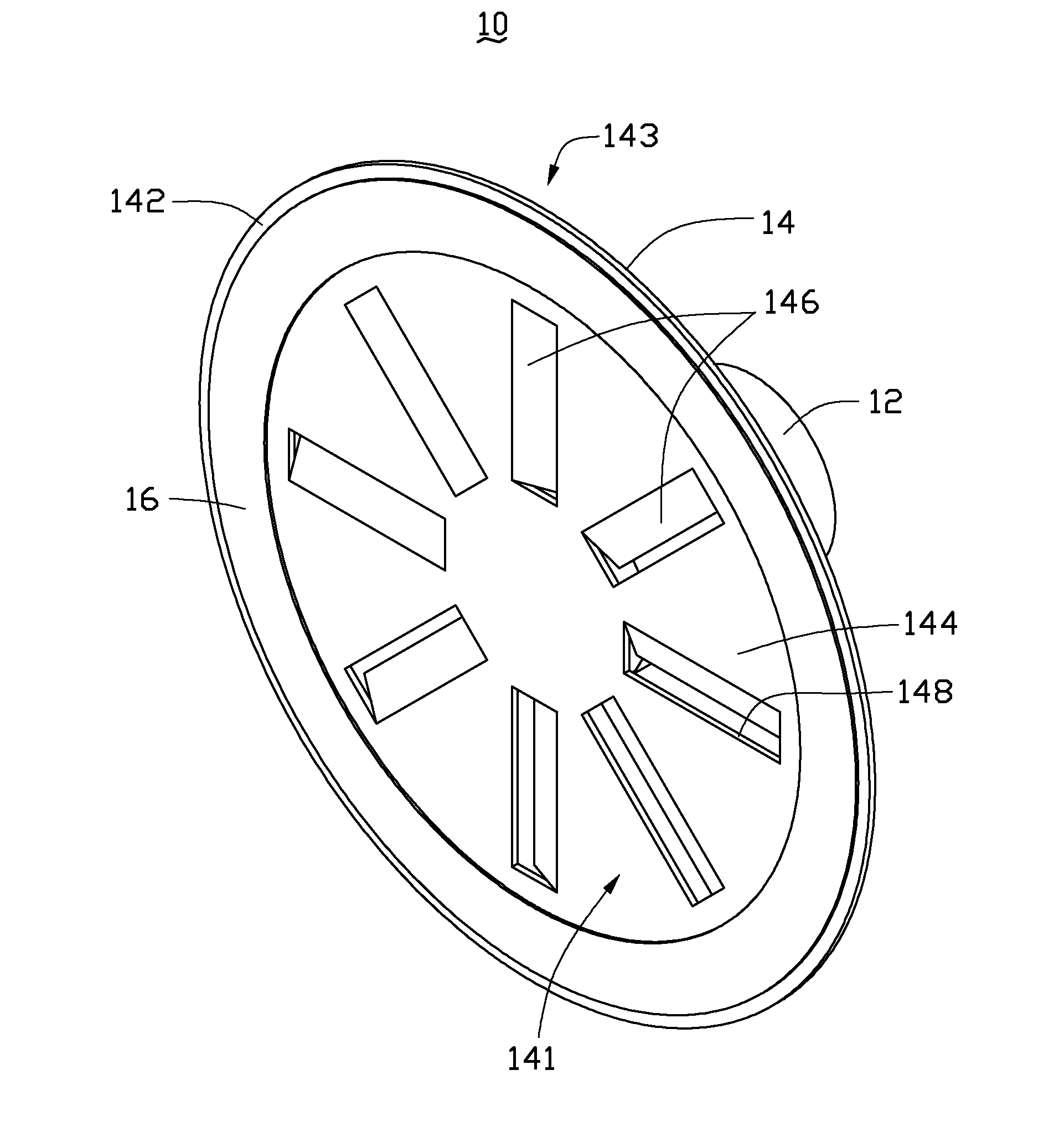
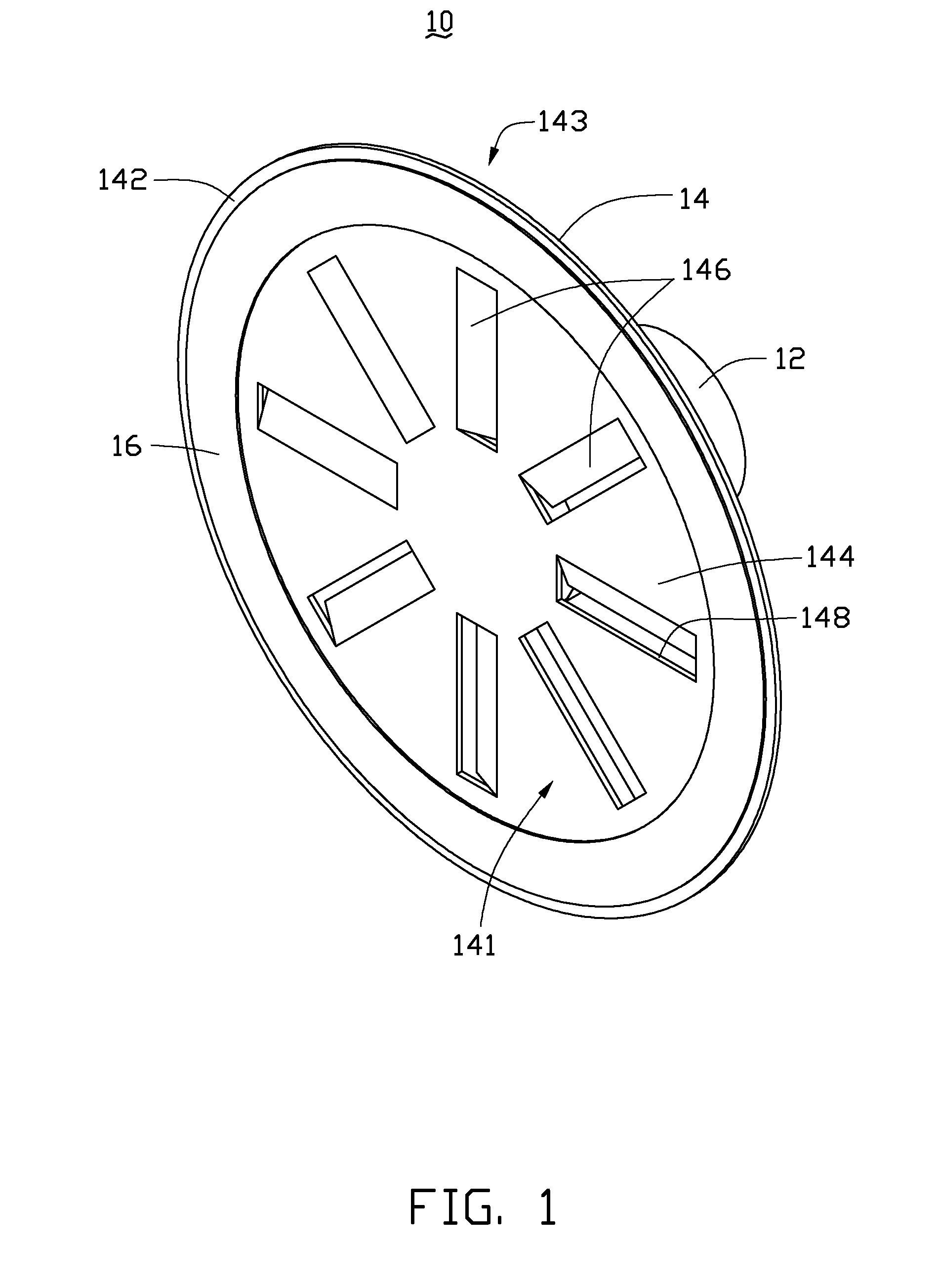
[0011]FIG. 1 shows a color wheel unit 10 of the disclosure. The color-wheel unit 10 includes a motor 12 and a color wheel14. The color wheel 14 has two surfaces, a light-irradiated surface 141 to receive lights and a non-irradiated surface 143 opposite to the light-irradiated surface 141. The color wheel 14 has a light-irradiated area 142 and a non-irradiated area 144. The light-irradiated area 142 is positioned in an outer margin of the color wheel 14. The color wheel 14 has at least one phosphor layer 16 in the light-irradiated area 142. In the present embodiment, the phosphor layer 16 has a circular shape. The phosphor layer 16 may include a plurality of phosphor pieces discontinuously arranged in the light-irradiated area 142. A plurality of fan blades 146 are located in the non-irradiated area 144, which is positioned in an inner margin of the color wheel 14.

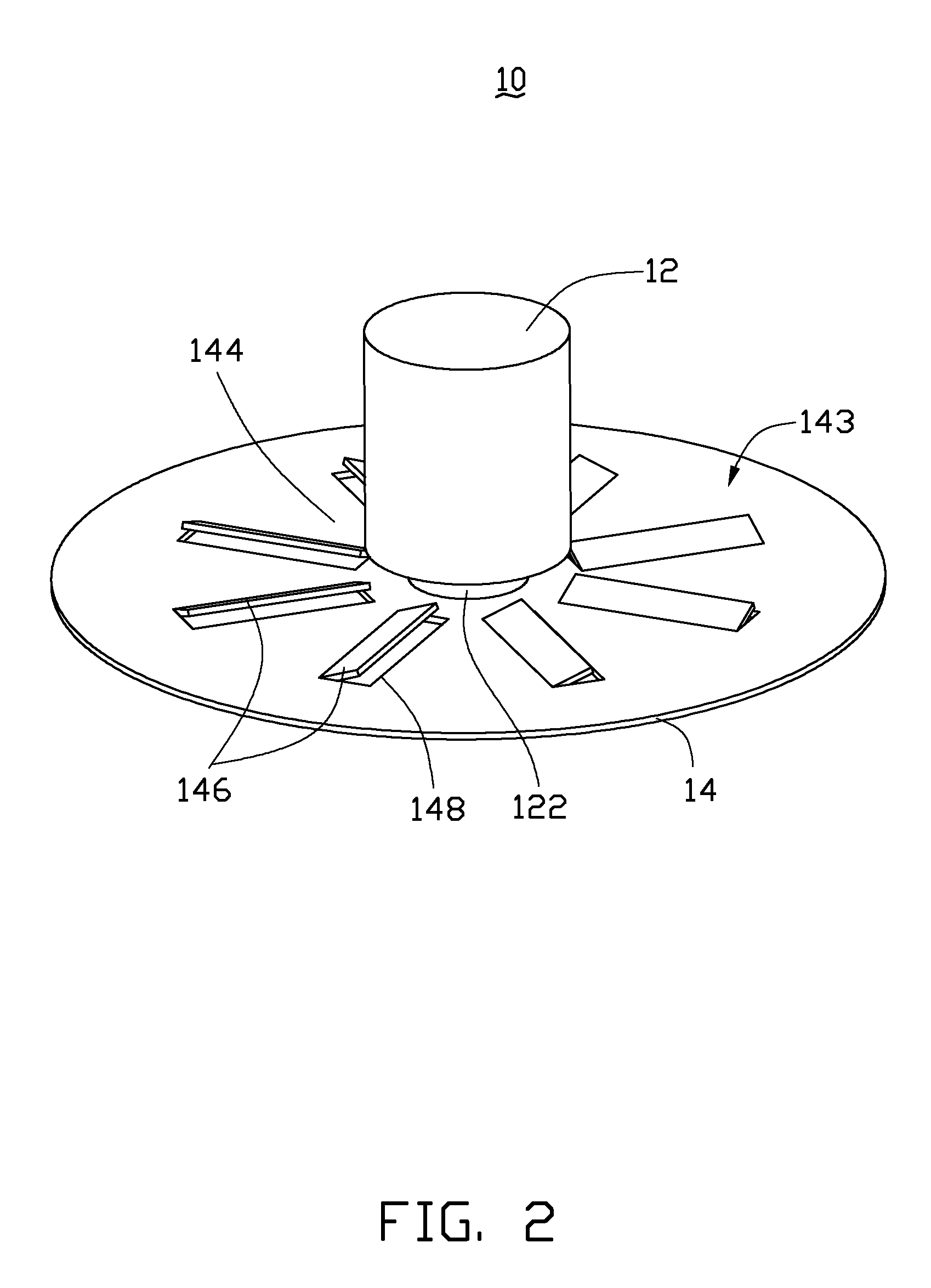
[0012]The color wheel 14 is c...


PUM


Abstract

A color wheel unit of a projector includes a motor and a color wheel. The color wheel is synchronized with the rotating motion of the motor. The color wheel has a light-irradiated area and a non-irradiated area. The light-irradiated area is positioned in an outer margin of the color wheel and at least a phosphor layer is located on the light-irradiated area. The non-irradiated area is positioned at the inner portion of the color chip. A number of fan blades are located in the non-irradiated area. The fan blades are synchronized with the rotating motion of the color wheel that generates air flow to enhance heat dissipation efficiency of the color wheel.

Description

BACKGROUND[0001]1. Technical Field[0002]The disclosure is related to a color wheel unit, and particularly to a color wheel unit having fan blades for improving heat dissipation efficiency.[0003]2. Description of Related Art[0004]Light sources of current projectors, such as high-pressure mercury-vapor lamp, tungsten-halogen lamps, and metal-halogen lamps, are known to consume high power, with a short lifetime, as well they are bulky, and generate high heat. Not only light sources but also other components, such as color wheel illuminated by light sources, are heat generators. Color wheel units are driven by motors. Radiation of light from the light source accumulates heat on the color wheel. Both active motors and passive color wheels produce heat and require heat dissipation devices to cool down. These heat-generating devices need cooling devices for heat dissipation. However, the color wheel units of current projectors are used to filter light of different colors and have no indepe...

Claims


Application Information

Patent Timeline
IPC IPC(8): G03B21/14
CPCG03B21/16G03B33/08G03B21/204
Inventor HUANG, KAISUN, MING-CHIH
Owner HON HAI PRECISION IND CO LTD
Why Eureka
Try Eureka