Multi-interface
- Summary
- Abstract
- Description
- Claims
- Application Information
AI Technical Summary
Benefits of technology
Problems solved by technology
Method used
Image
Examples
first embodiment
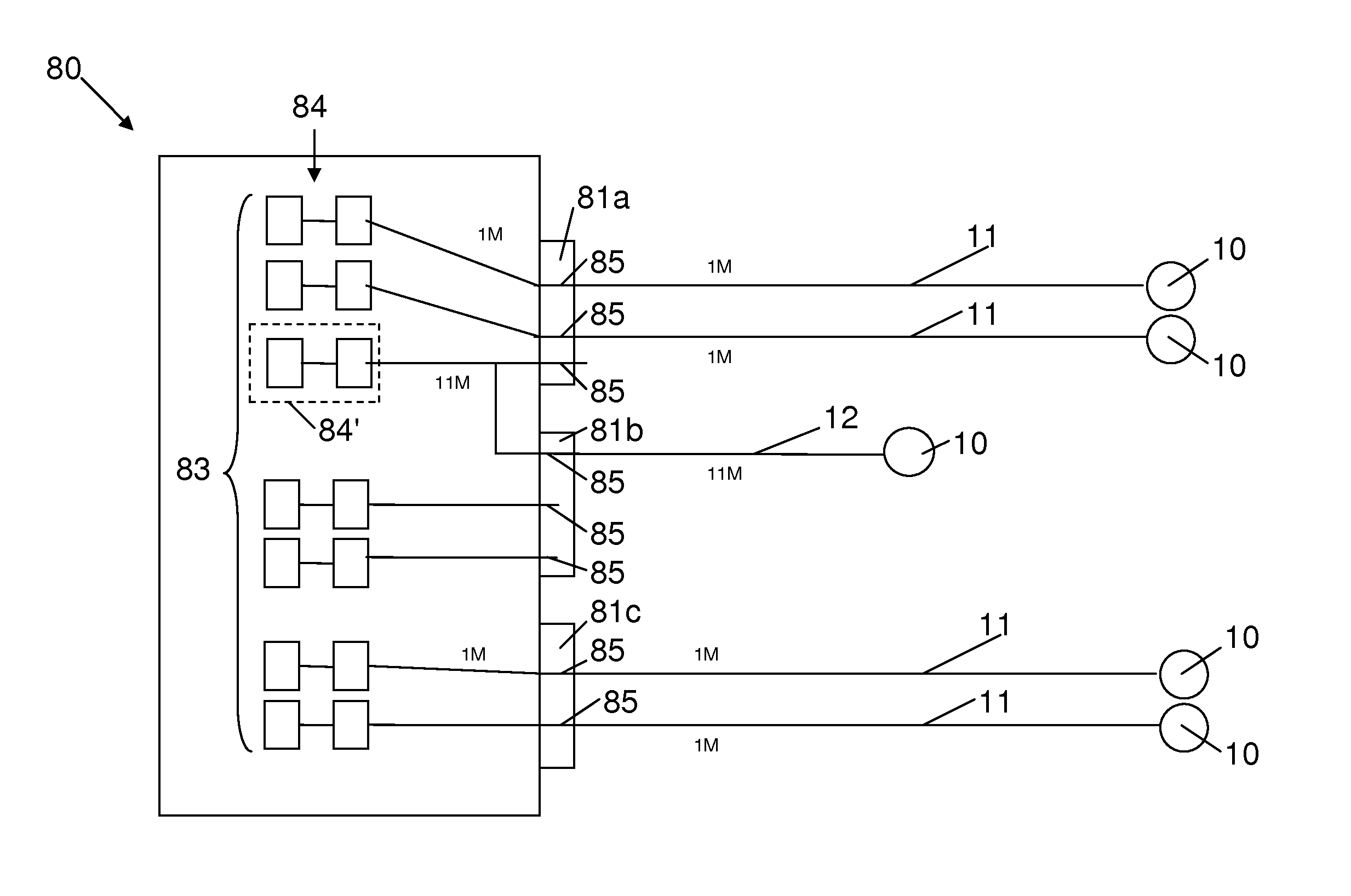
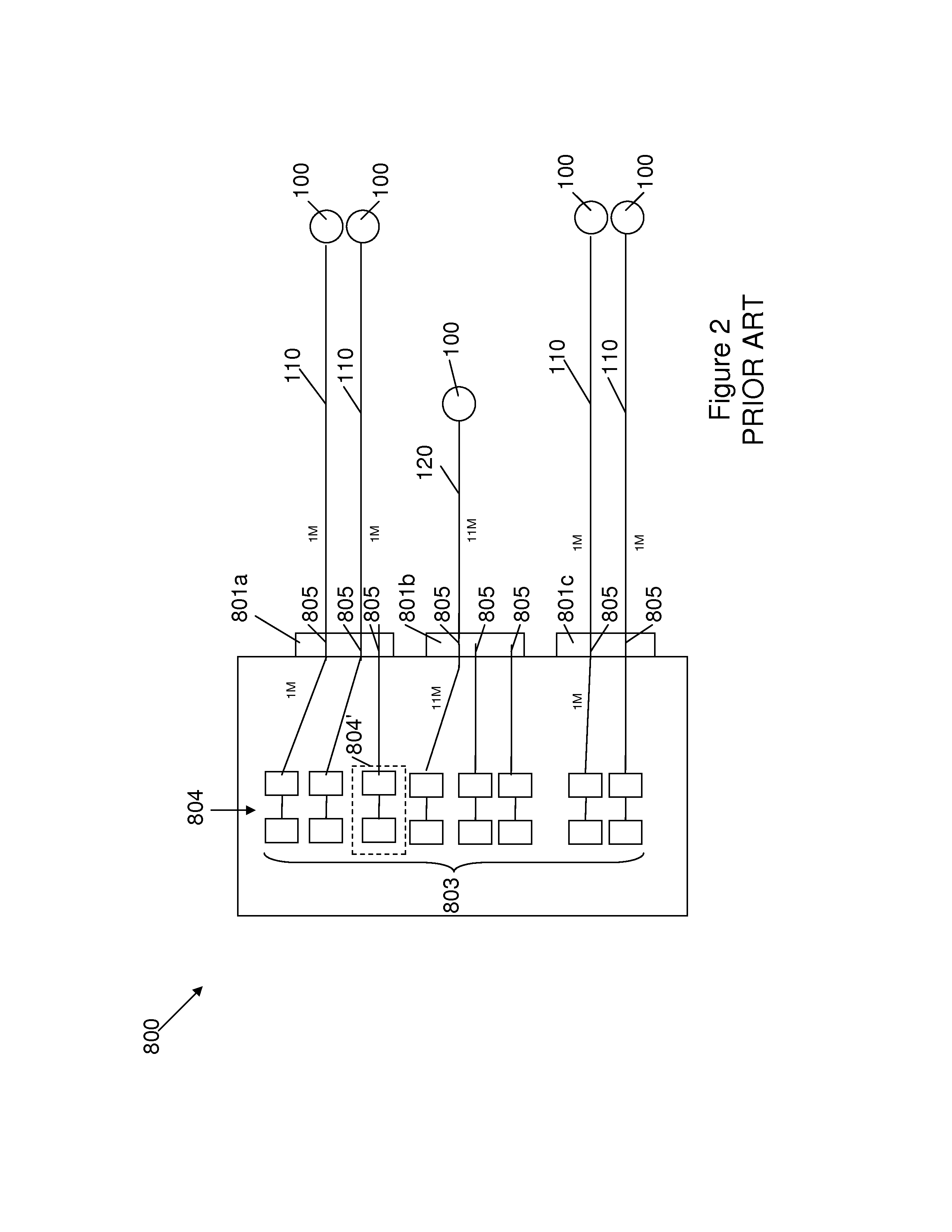
[0039]An RDC according to this invention is illustrated schematically in FIG. 3. The RDC 80 shown in FIG. 3 has the same number of connectors 81 and the same number of pins 85 as the RDC 800 described above. However, the number of I / O interfaces 83 has been reduced from eight to seven such that there are only seven sets of hardware 84 within RDC 80. The connections to the pins 85 is the same as that described above with reference to FIG. 2 in that connector 81 has two pins 85 connected to 1M designated wire routes 11, connector 81b has one pin 85 connected to 11M designated wire route, and connector 81c has both pins 85 connected to 1M designated wire routes 11. The wire routes 11, 12 connect to various sensors, effectors, etc. 10.
[0040]The only difference between the RDC 80 of FIG. 3 and the RDC 800 of FIG. 2 is that one of the interfaces includes hardware 84′ (indicated in broken line) electrically connected to a pin 85 of connector 81a, and is also electrically connected to a pin...
second embodiment
[0042]FIG. 4 illustrates schematically a simplified RDC according to a The RDC 810 includes two connectors 811a and 811b. The RDC 810 has two interfaces 813, one of which is a multi-interface. Single interface hardware 814 is electrically connected to a pin 815 of connector 811a. Multi-interface hardware 814′ is electrically connected to a pin 815 of connector 811a and also to a pin 815 of connector 811b.
[0043]FIG. 5 illustrates how the RDC 810 of the second embodiment can be used as a common RDC (cRDC) within an avionics architecture. Each cRDC 810 has identical hardware. The five cRDCs 810 are labelled (a)-(e) in FIG. 5. The two connectors 811a and 811b shown in FIG. 4 will be referred to as “first” and “second” connectors, respectively, in the following.
[0044]cRDC 810(a) has its first connector connected to 1M designated wire route bundle 11. Since it is not possible to connect more than one pin of a multi-interface at any instance, the second connector of cRDC 810(a) is unconn...
fourth embodiment
[0047]FIG. 6 illustrates an RDC according to a The RDC 820 has three connectors 821a, 821b and 821c, and a single I / O interface 823. The interface 823 includes multi-interface hardware 824′ electrically connected to a pin 825 of each of the three connectors 821a-821c. Comparing the RDC 820 of FIG. 5 with the RDC 810 of FIG. 4, it can be seen that the multi-interface of this invention is not limited to making connections to only two connectors but can be adapted for connection to three (or more) connectors. Increasing the number of pins on different connectors that the same interface hardware is connected to potentially increases the number of different wire route designations that can access the interface hardware, thus further increasing the flexibility of the cRDC design. However, the number of spare pins also decreases and so there is a corresponding trade off with space requirements.
[0048]FIG. 7 illustrates an RDC according to a fourth embodiment. The RDC 830 includes a multi-p...
PUM
 Abstract
Description
Claims
Application Information
 - R&D
- Intellectual Property
- Life Sciences
- Materials
- Tech Scout
- Unparalleled Data Quality
- Higher Quality Content
- 60% Fewer Hallucinations
Browse by: Latest US Patents, China's latest patents, Technical Efficacy Thesaurus, Application Domain, Technology Topic, Popular Technical Reports.
© 2025 PatSnap. All rights reserved.Legal|Privacy policy|Modern Slavery Act Transparency Statement|Sitemap|About US| Contact US: help@patsnap.com


