Electronic equipment

a technology of electronic equipment and input, applied in the direction of mechanical pattern conversion, instruments, cathode-ray tube indicators, etc., can solve the problems of insufficient connection between the related arts and the documents 1 to 4 and the inability to correctly detect the line of sight, and achieve the effect of increasing the recognition rate of eye-controlled inpu

Inactive Publication Date: 2013-07-11
KYOCERA CORP
View PDF9 Cites 99 Cited by
  • Summary
  • Abstract
  • Description
  • Claims
  • Application Information

AI Technical Summary

Benefits of technology

[0012]Another object of the present invention is to provide electronic equipment capable of increasing a recognition rate of an eye-controlled input.

Problems solved by technology

Accordingly, on the assumption that such an eye-controlled input device is incorporated in relatively small electronic equipment such as a mobile terminal, the related arts respectively described in the documents 1 to 4 are not adequate because the device is relatively large.
That is, in a case that an eye and a device are separate from each other, there is a possibility that a line of sight cannot be correctly detected.

Method used


Image

  • Electronic equipment
  • Electronic equipment
  • Electronic equipment

Examples


Embodiment Construction

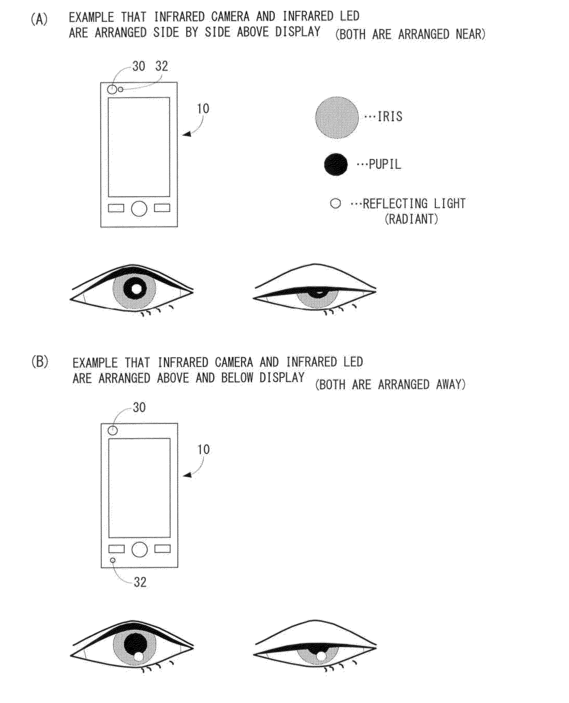
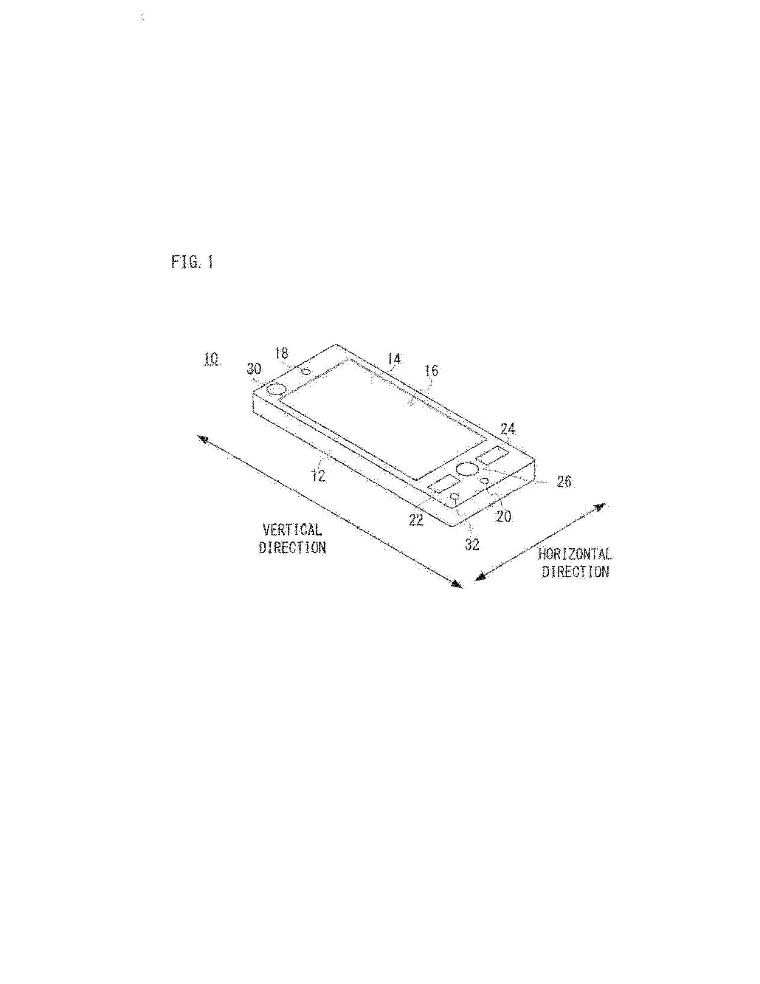
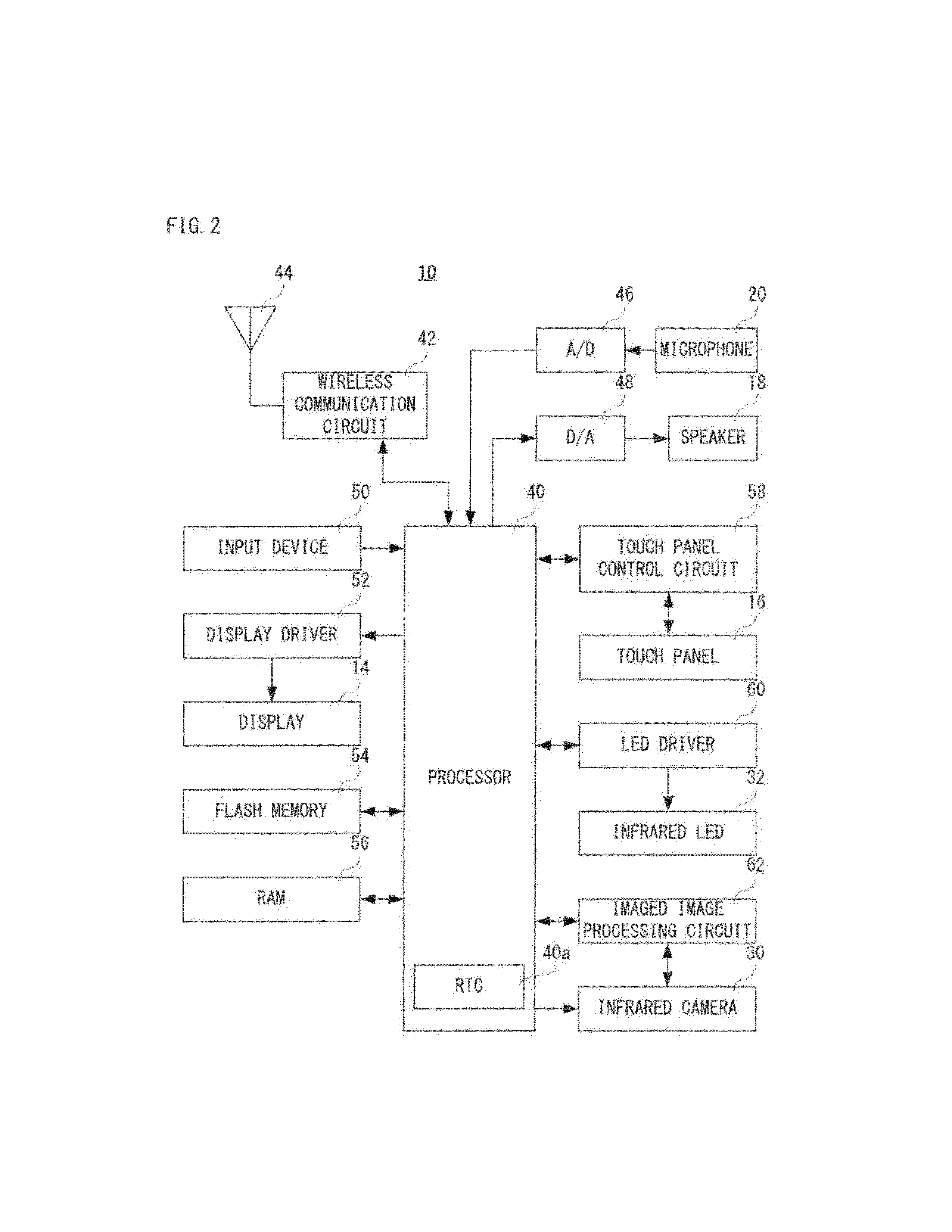
[0047]With referring to FIG. 1, a mobile phone 10 of an embodiment according to the present invention is a so-called smartphone, and includes a longitudinal flat rectangular housing 12. A display 14 constituted by a liquid crystal, organic EL or the like, which functions as a display portion, is provided on a main surface (front surface) of the housing 12. A touch panel 16 is provided on the display 14. A speaker 18 is housed in the housing 12 at one end of a longitudinal direction on a side of the front surface, and a microphone 20 is housed at the other end in the longitudinal direction on the side of the front surface. As a hardware key constituting an inputting portion together with the touch panel 16, a call key 22, an end key 24 and a menu key 26 are provided. Furthermore, an infrared camera 30 is provided at a left side of the speaker 18, and an infrared LED 32 is provided at a left side of the microphone 20. The infrared camera 30 and the infrared LED 32 are provided such th...


PUM


Abstract

A mobile phone which is an example of electronic equipment includes an infrared camera and an infrared LED. The infrared camera is arranged above a display and the infrared LED is arranged below the display. A user, by an eye-controlled input, designates a button image or a predetermined region on a screen. When a line of sight is to be detected, an infrared ray (infrared light) emitted from the infrared LED arranged below the display is irradiated to a lower portion of a pupil. Accordingly, even in a state that the user slightly closes his/her eyelid, the pupil and a reflected light of the infrared light can be imaged.

Description

CROSS REFERENCE OF RELATED APPLICATION[0001]The disclosure of Japanese Patent Application No. 2012-1114 is incorporated herein by reference.BACKGROUND OF THE INVENTION[0002]1. Field of the Invention[0003]The present invention relates to electronic equipment, and more specifically, electronic equipment provided with a display, for example.[0004]2. Description of the Related Art[0005]An example of a related art is disclosed in Japanese Patent Application Laying-Open No. 2003-196017 [G06F 3 / 033, G06F 3 / 00, G06T 1 / 00, G06T 7 / 60] (document 1) laid-open on Jul. 11, 2003. A data input device of this document 1 displays an input data group of a menu or a keyboard on a display, images an eye portion of a user of the device with a camera, determines a direction of a line of sight of the user in the imaged image, determines input data located in the direction of the line of sight, and outputs determined input data to external equipment, etc.[0006]Another example of a related art is disclosed i...

Claims


Application Information

Patent Timeline
Patent Type & Authority Applications(United States)
IPC IPC(8): G06F3/01
CPCG06F3/013
Inventor TANAKA, NAONAGATA, KEISUKEKIDA, YOSHINORI
Owner KYOCERA CORP
Why Eureka
Try Eureka