
Method and apparatus for controlling a frequency converter

a frequency converter and frequency technology, applied in the field of frequency converters, can solve problems such as potential danger of subsynchronous resonance grids, large loss of transmission capacity, and problems such as problematic effects, and achieve the effect of destroying the subsynchronous resonance in the power grid

Active Publication Date: 2013-07-11
INGETEAM POWER TECH
View PDF6 Cites 37 Cited by
  • Summary
  • Abstract
  • Description
  • Claims
  • Application Information

AI Technical Summary

Benefits of technology

The control method described in this patent can be easily integrated into existing systems by updating the software used in the control unit of a converter. Its technical effect is to provide an improved control method that can be easily integrated into existing systems.

Problems solved by technology

The existence of high inductive impedance in a power grid will mean a greater loss in its transmission capacity.
This phenomenon is due to the voltage drop that occurs in the inductive impedance of the cable when current circulates through it, and it can become important in certain cases that combine factors such as long lengths of cable and high power consumption (high circulation of current through the power grid).
Inserting series capacitors in highly inductive power grids is effective when solving the problem of the loss of transmission capacity of a grid, but in turn, results in problematic effects when considered from the point of view of the stability of the compensated power grid.
Grids with subsynchronous resonance are potentially dangerous grids for integrating generation components that are based on generation turbines with rotary shafts having a low-frequency mechanic oscillation.
This effect could result in a failure of the generator shaft.
This case corresponds to a problem specific to the natural interaction between two parts of a power system, the power grid adjusted with capacitors and the generator, where the mechanical mass of a synchronous generator resonates with the subsynchronous frequency of the grid equivalent impedance of the power grid.
This is the interaction of frequency converter controls with compensated grids, a phenomenon that can cause the loss of control of the flow of energy through the converter, which may destabilize the power grid itself.

Method used


Image

  • Method and apparatus for controlling a frequency converter
  • Method and apparatus for controlling a frequency converter
  • Method and apparatus for controlling a frequency converter

Examples


Embodiment Construction

[0031]The detailed description of the various aspects of the invention will be developed based on a doubly-fed topology power generation application. A person skilled in the art might understand that the invention described is applicable to any application including at least one frequency converter connected to the grid. As proof of the above, examples such as power generation or consumption applications can be cited in which all of the energy flows through the frequency converter (full converter), HVDC applications for power distribution or HVAC applications for power distribution.

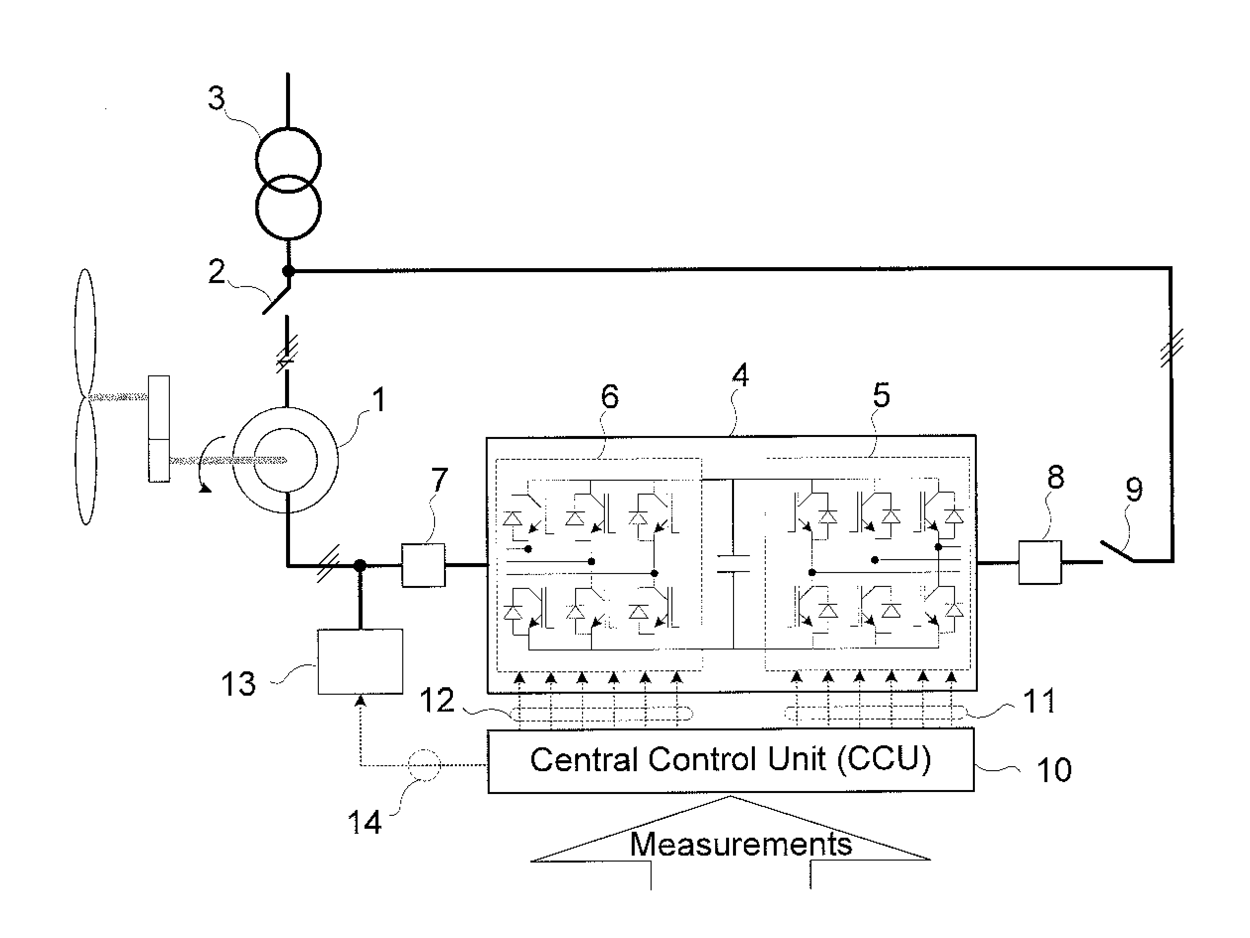
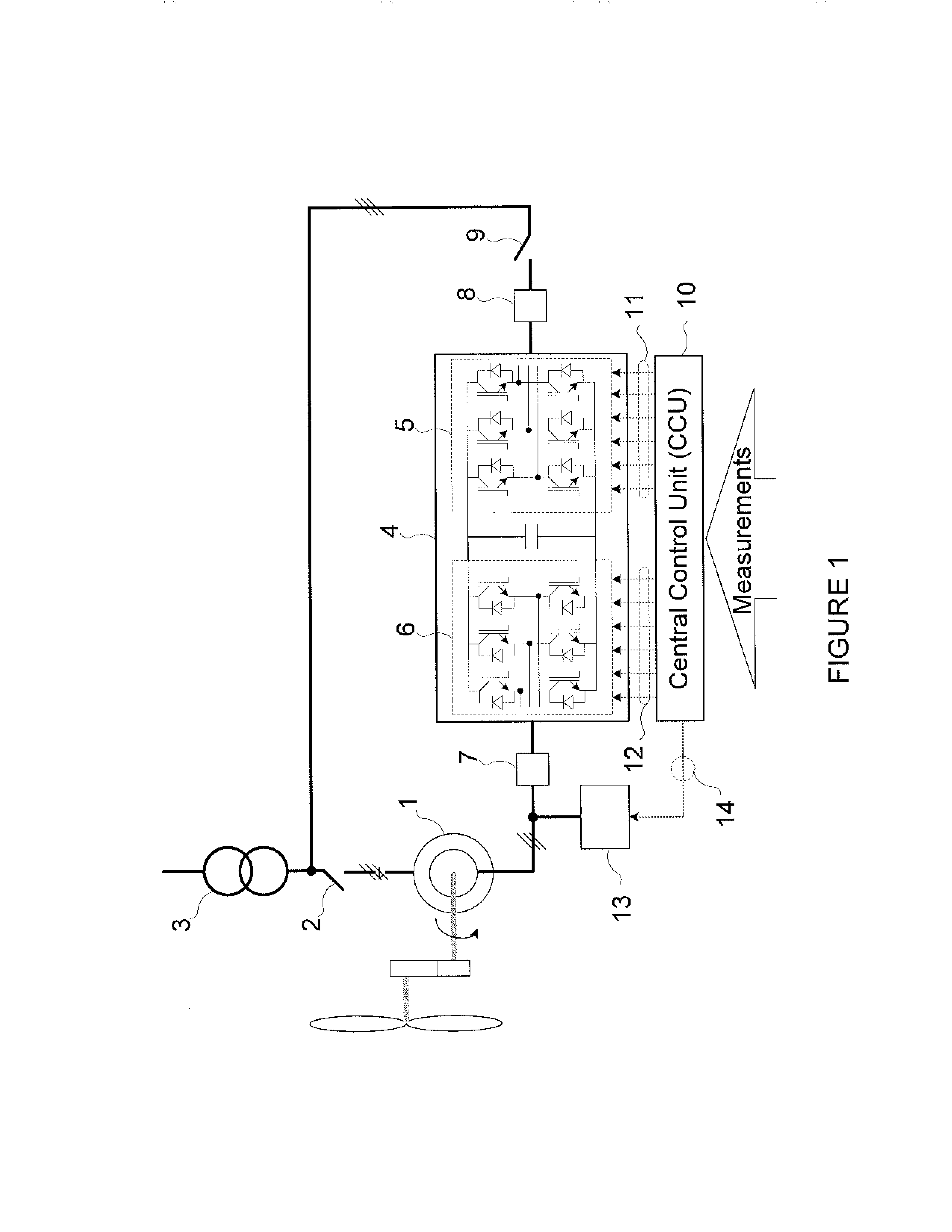
[0032]The doubly-fed topology consists of a doubly-fed asynchronous generator wherein the stator terminals are connected directly to the power grid and wherein the rotor terminals are connected to a frequency converter that is in turn connected to the power grid.

[0033]FIG. 1 shows a single-line wire diagram of a wind power application based on a doubly-fed topology. The diagram shows the different parts t...


PUM


Abstract

An apparatus and method of controlling a frequency converter is provided. First, subsynchronous components in the electrical grid are identified using voltage measurements of the electrical grid. The subsynchronous components of the electrical grid are then used to determine set points for damping currents. These damping currents are then added to current set points calculated by power regulation loops to generate total current set points. Thereafter, the frequency converter is controlled based on the total current set points.

Description

CROSS-REFERENCE TO RELATED PATENT APPLICATION[0001]This application claims priority from U.S. Provisional Patent Application No. 61 / 583,449 filed on Jan. 5, 2012 in the U.S. Patent Trademark Office, the disclosure of which is incorporated herein in its entirety by reference.BACKGROUND OF THE INVENTION[0002]1. Field of the Invention[0003]Apparatuses and methods consistent with the present invention relate to a frequency converter utilized in a wind turbine generator.[0004]2. Description of the Related Art[0005]Power grids are the part of a power supply system and have the components necessary to transfer the electric power generated by power generating units across long distances to points of power consumption. Most power grids installed today carry energy as an alternating voltage and current. It is worth highlighting that the number of power grids carrying energy as continuous voltage and current (DC) is increasing due to the advantages they offer in terms of energy efficiency in l...

Claims


Application Information

Patent Timeline
Patent Type & Authority Applications(United States)
IPC IPC(8): H02M3/335
CPCH02M3/335H02J3/386H02P9/105H02P9/007H02J3/48H02J3/1842Y02E10/763H02J3/24H02J2300/28H02J3/381H02J3/46Y02E10/76H02J3/241H02M5/4585
Inventor OLEA, ENEKORUIZ, JOSUELORRIAGA, JOSUAURTENETXEA, SERGIOCARCAR, AINHOAGIL, BEATRIZ
Owner INGETEAM POWER TECH
Learn More