Dual-polarization multi-wavelength coherent receiver frontend

a receiver and multi-wavelength technology, applied in the field of optical communication systems and methods, can solve the problems of increasing capacity, however, and requiring more complex receiver frontends

Inactive Publication Date: 2013-07-11
ALCATEL LUCENT SAS
View PDF7 Cites 8 Cited by
  • Summary
  • Abstract
  • Description
  • Claims
  • Application Information

AI Technical Summary

Problems solved by technology

This increased capacity does, however, typically require more complex receiver frontends.

Method used


Image

  • Dual-polarization multi-wavelength coherent receiver frontend
  • Dual-polarization multi-wavelength coherent receiver frontend
  • Dual-polarization multi-wavelength coherent receiver frontend

Examples


Embodiment Construction

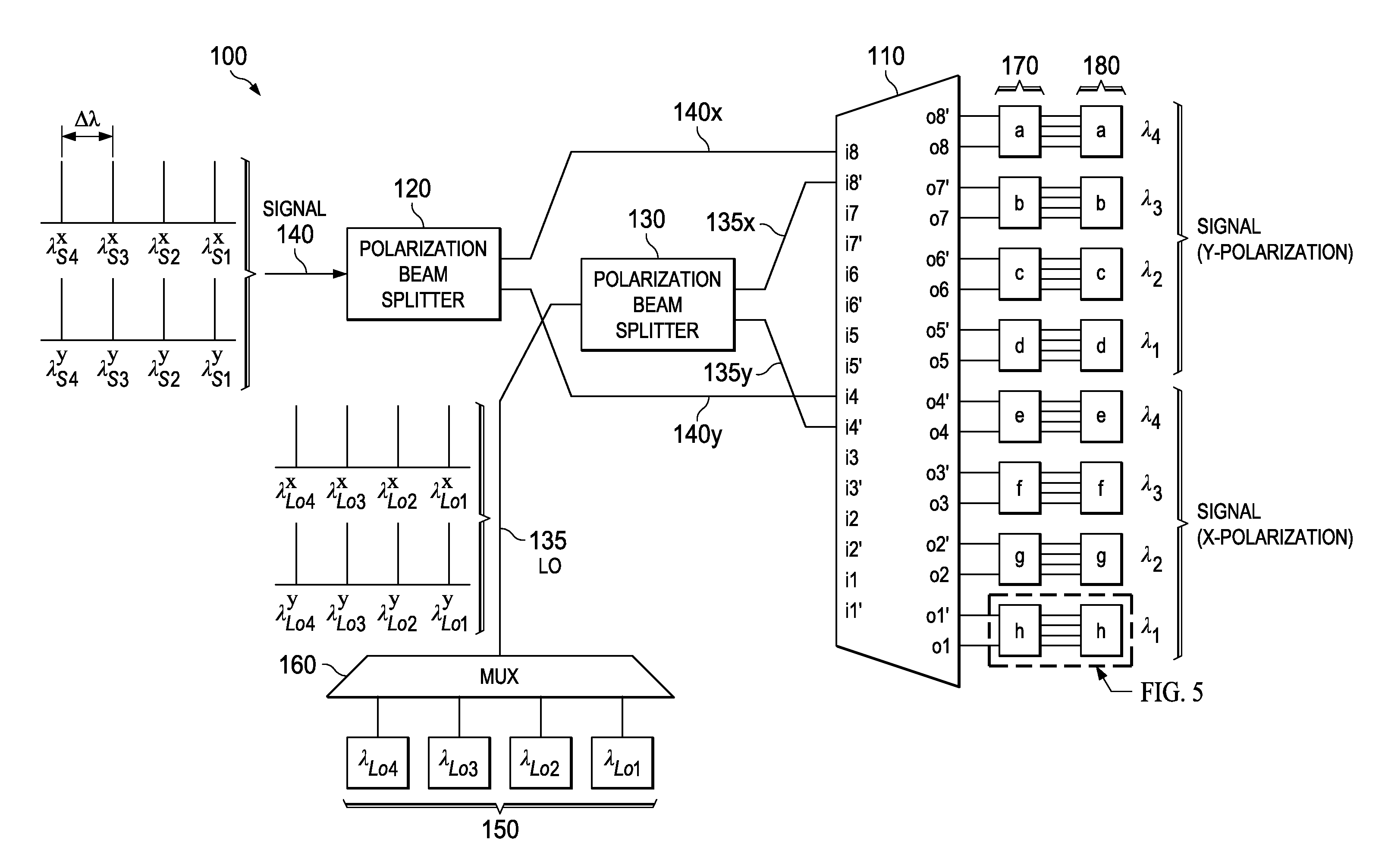
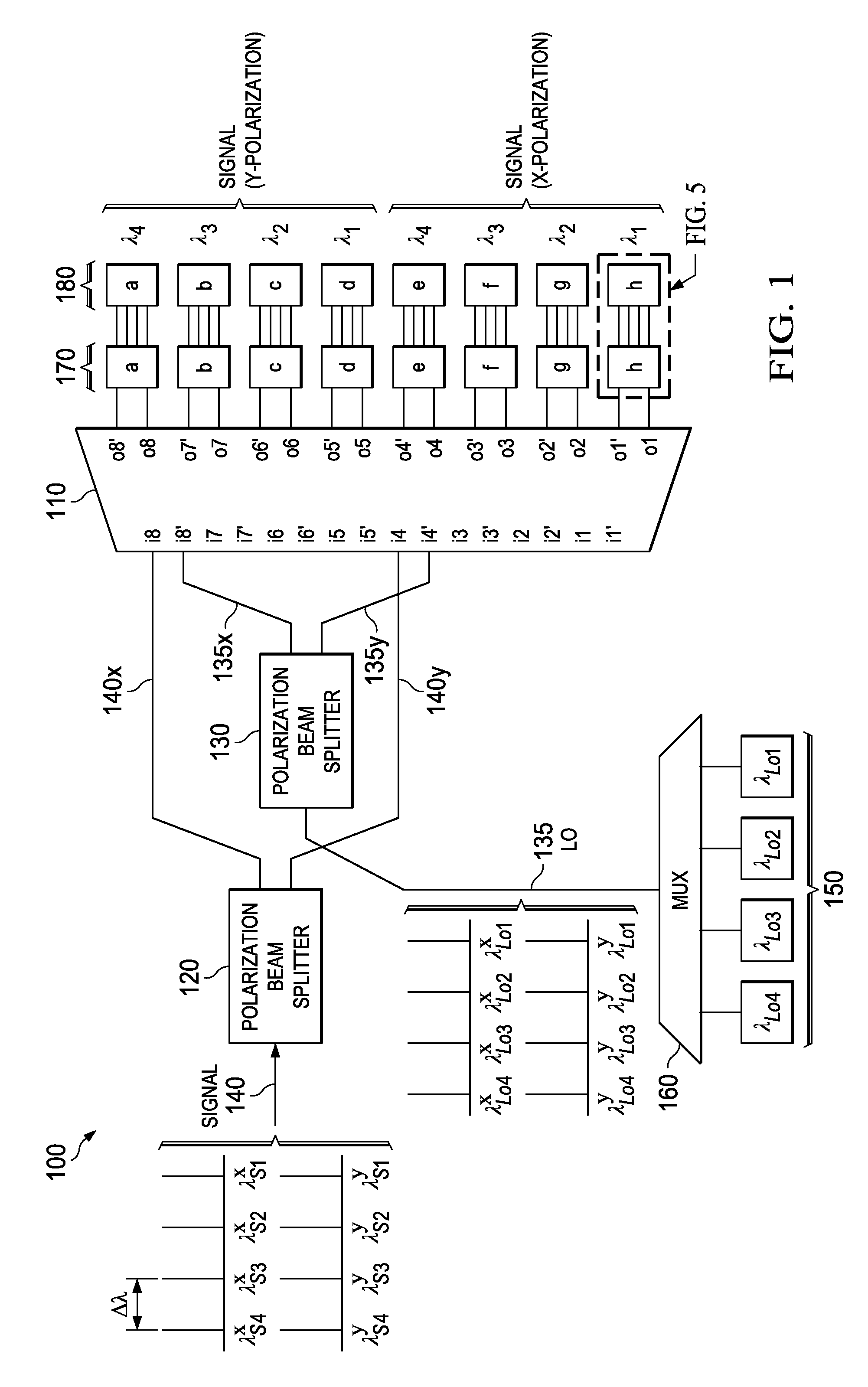
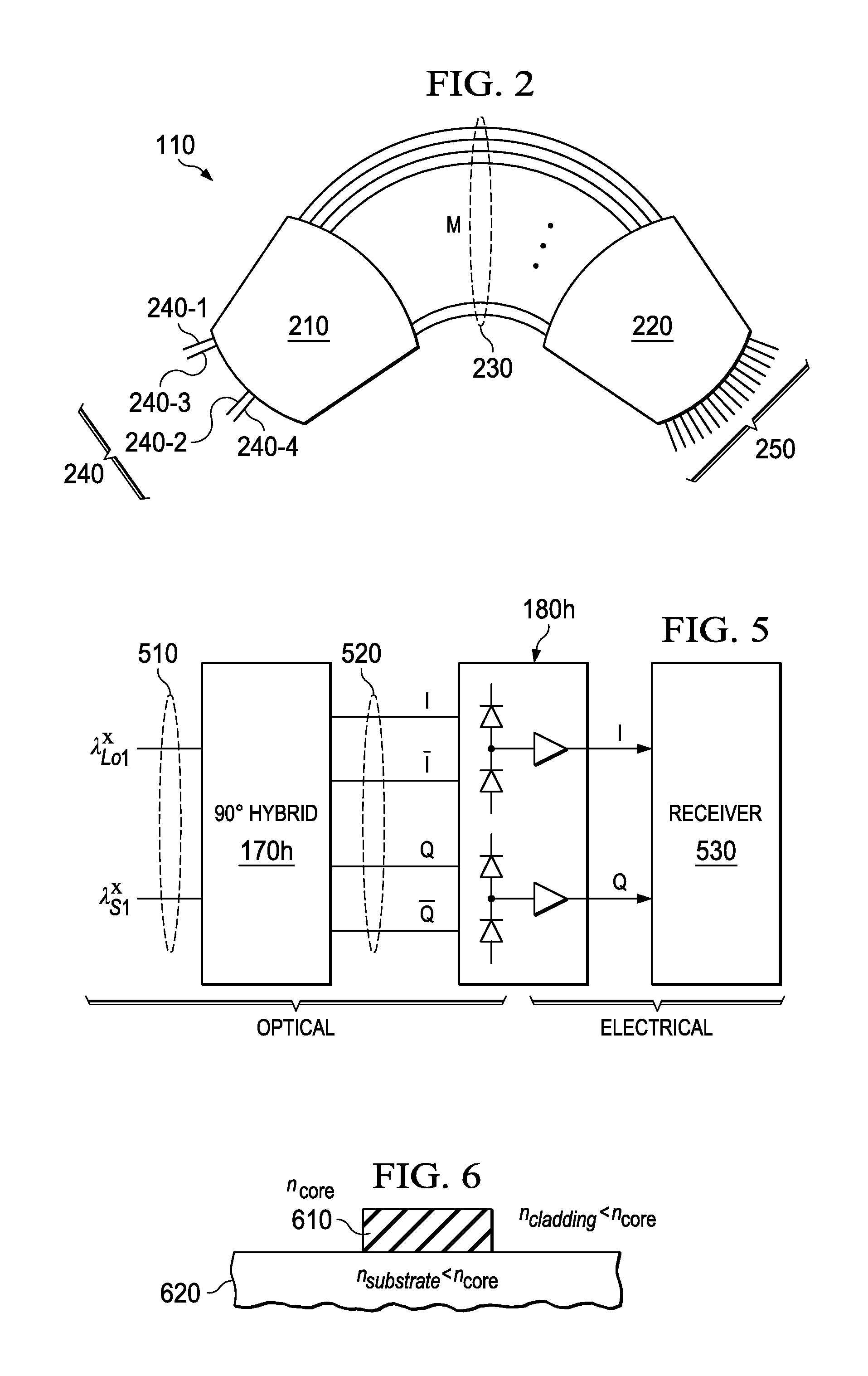
[0014]Embodiments described herein provide a single device that integrates a demultiplexer (e.g. an AWG), polarization beam splitters (PBS), and 90° hybrid on a single PLC substrate. Various embodiments further provide a demultiplexer (demux) type that receives a multi-wavelength (e.g. wavelength-division multiplexed, or WDM) data-bearing signal comb at a first input port and an LO comb at another input port. At the demux output, each wavelength component of the signal and its corresponding LO are then routed to two separate adjacent waveguides, where the signal and the LO can be further coupled to a 90° hybrid mixer. Some embodiments that implement dual-polarization reception employ the same demux to independently route each polarization component to a different set of 90° hybrid mixers.

[0015]Various embodiments described here employ a waveguide material with relatively low refractive index (RI or ni) for optical components and waveguide interconnects to reduce insertion loss and t...


PUM


Abstract

An apparatus includes an AWG demultiplexer having first and second adjacent input ports. The first input port is configured to receive a first WDM data-bearing signal, the second input port is configured to receive a first WDM LO signal. The first and second input ports are located such that individual channels of said WDM data-bearing signal route to a first set of output ports, and individual channels of said WDM LO signal route to a second set of output ports interleaved with the first set.

Description

TECHNICAL FIELD[0001]This disclosure is directed, in general, to optical communications systems and methods.BACKGROUND[0002]This section introduces aspects that may be helpful to facilitating a better understanding of the inventions. Accordingly, the statements of this section are to be read in this light and are not to be understood as admissions about what is in the prior art or what is not in the prior art.[0003]It is expected that future optical networks will employ coherent polarization-multiplex quadrature phase-shift-keying (PM-QPSK) transmission format for efficient use of spectral bandwidth. Such formats will most likely be used in long-haul and ultra-long-haul (LH / ULH) dense wavelength-division multiplexing (DWDM) systems. Furthermore, to overcome the bottleneck in transponder interface rates, next-generation coherent receivers are expected to employ multi-wavelength reception to increase the degree of optical parallelism, hence increasing system capacity. This increased c...

Claims


Application Information

Patent Timeline
Patent Type & Authority Applications(United States)
IPC IPC(8): H04J14/02
CPCH04J14/002H04B10/615H04J14/06G02B6/272
Inventor RASRAS, MAHMOUD
Owner ALCATEL LUCENT SAS
Why Eureka
Try Eureka