
Handheld power tool having a planetary gear

Active Publication Date: 2013-07-11
ROBERT BOSCH GMBH
View PDF3 Cites 6 Cited by
  • Summary
  • Abstract
  • Description
  • Claims
  • Application Information

AI Technical Summary

Benefits of technology

The present invention aims to provide a power tool that can safely and reliably detect extreme loads during operation.

Problems solved by technology

The disadvantage of the above is that, in handheld power tools of this type, a kinetic energy of rotation supplied to the drive shaft by the planetary gear may be converted into a rotation of the gear housing and thus of the handheld power tool in the event of extreme load conditions, e.g., in the event of so-called hard screw applications during the operation of cordless screwdrivers or cordless combi drills which may occur during metal screw fittings, for example, and may cause a spontaneous blocking of the drive shaft.
This may result in an impact-like load on components of the planetary gear, for example, and thus in them being damaged or destroyed.

Method used


Image

  • Handheld power tool having a planetary gear
  • Handheld power tool having a planetary gear
  • Handheld power tool having a planetary gear

Examples


Embodiment Construction

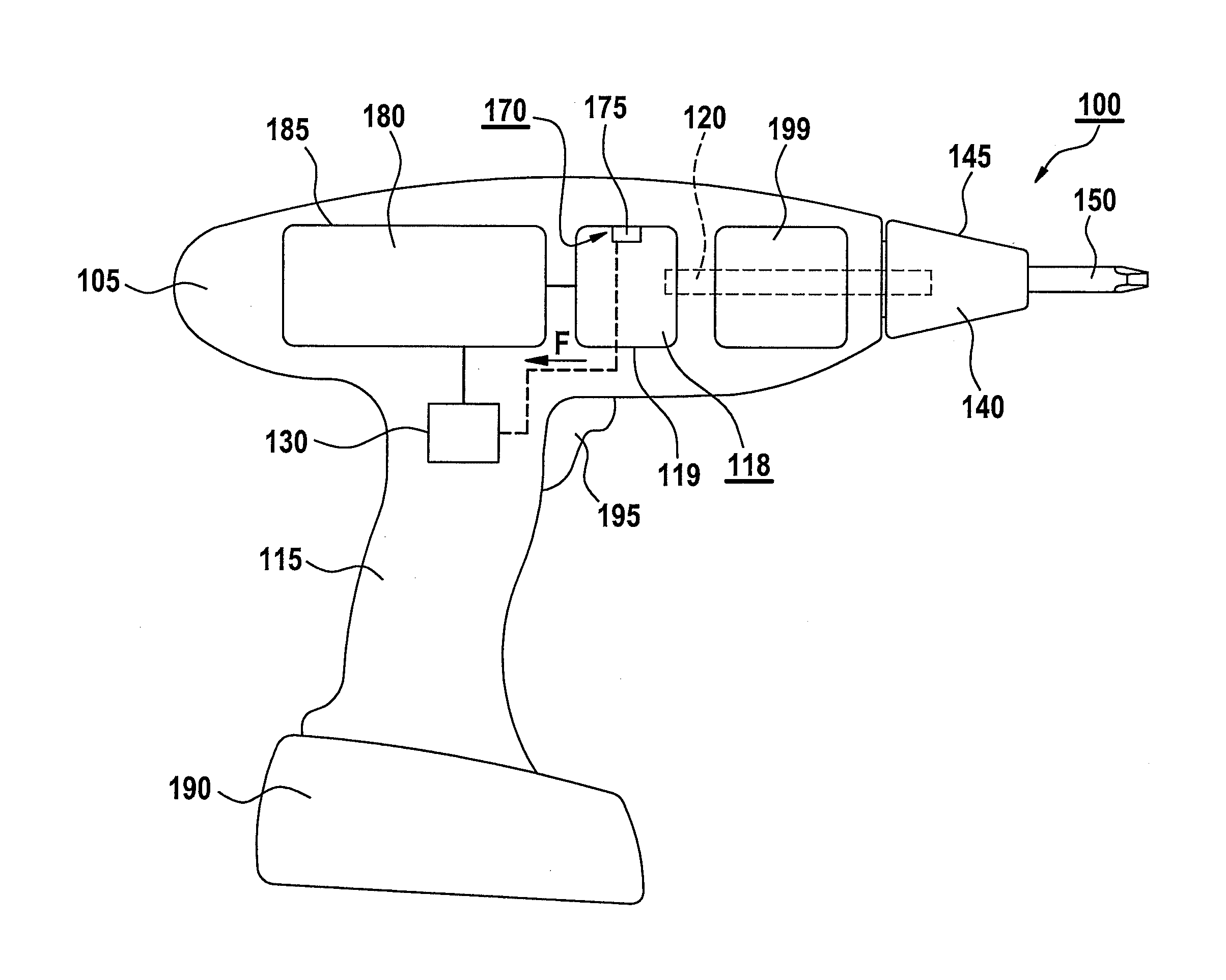
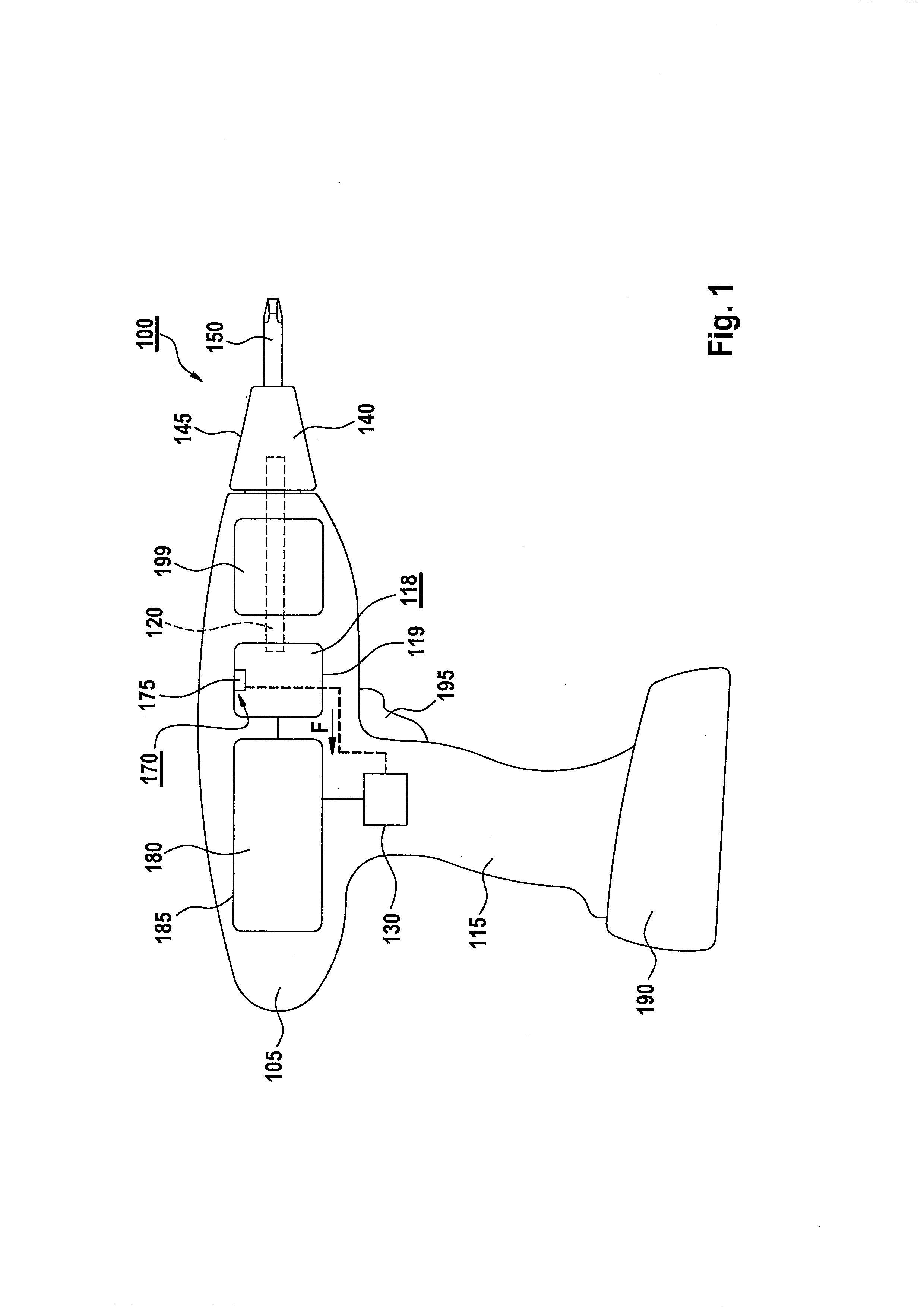
[0033]FIG. 1 shows an exemplary handheld power tool 100 having a tool housing 105 provided with a handle 115, a tool holder 140 designed for holding an insert tool 150 being situated on this tool housing. According to one specific embodiment, handheld power tool 100 is connectable mechanically and electrically to a battery pack 190 for a mains-independent power supply. In FIG. 1, handheld power tool 100 is designed as a cordless combi drill as an example. Therefore, tool holder 140 has a drill chuck 145 as an example.

[0034]It is, however, pointed out that the present invention is not limited to cordless combi drills, but may rather be used with various handheld power tools in which a tool is set into rotation regardless of whether the handheld power tool is mains-operatable or operatable mains-independently using battery pack 190, e.g., with a screwdriver or a cordless screwdriver, a percussion drill, or a cordless percussion drill, etc.

[0035]An electric drive motor 180, which is su...


PUM


Abstract

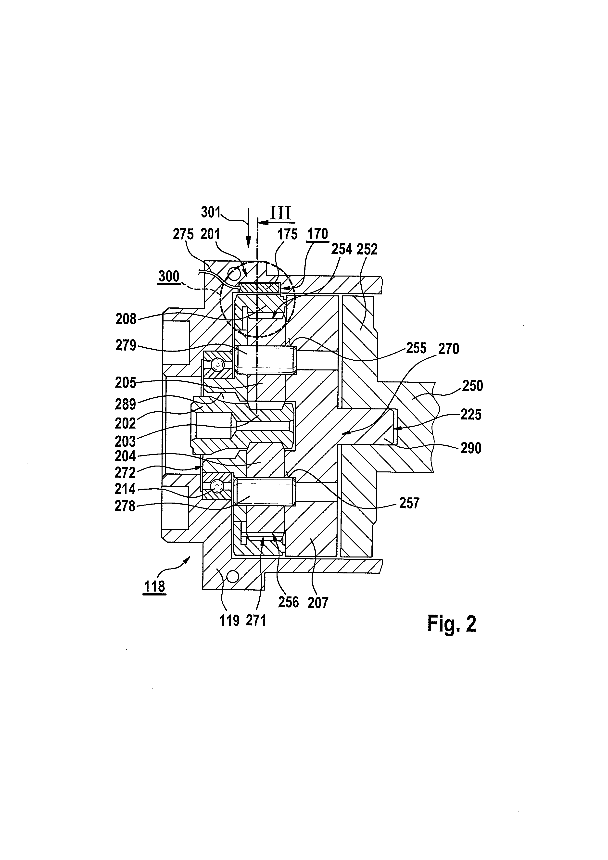
In a handheld power tool having a planetary gear, drivable by a motor, for driving a drive shaft in a first or second predefined direction of rotation, the planetary gear being situated in a gear housing and having at least one planetary stage to which an annulus gear situated in the gear housing is assigned, in the area between the annulus gear and the gear housing, at least one sensor element is situated which is designed to enable a detection of a torque which acts in the first or the second direction of rotation and is transferable to the annulus gear via the drive shaft during the operation of the handheld power tool.

Description

CROSS REFERENCE[0001]The present application claims the benefit under 35 U.S.C. §119 of German Patent Application No. DE 102012200334.7 filed on Jan. 11, 2012, which is expressly incorporated herein by reference in its entirety.FIELD[0002]The present invention relates to a handheld power tool having a planetary gear, drivable by a motor, for driving a drive shaft in a first or second predefined direction of rotation, the planetary gear being situated in a gear housing and having at least one planetary stage to which an annulus gear situated in the gear housing is assigned.BACKGROUND INFORMATION[0003]Conventional handheld power tools may, for example, be designed as cordless screwdrivers or cordless combi drills and have a planetary gear, situated in an associated gear housing, for driving a drive shaft rotatable in different directions of rotation. The planetary gear may be designed as a single-stage or multi-stage gear and may accordingly have one or multiple annulus gears situated...

Claims


Application Information

Patent Timeline
IPC IPC(8): F16H1/28
CPCF16H1/28B25B21/00Y10T477/33B25F5/001B25B23/147
Inventor SAUR, DIETMAR
Owner ROBERT BOSCH GMBH
Learn More