
Percussion instrument apparatus, system and process

a technology of percussion instruments and apparatuses, applied in the field of percussion instruments, components of percussion instruments, to achieve the effect of minimizing contact area, ensuring sound output according to the striking force, and reducing the time lag between the moment of striking and the output of sound

Active Publication Date: 2013-07-18
ROLAND CORP
View PDF13 Cites 37 Cited by
  • Summary
  • Abstract
  • Description
  • Claims
  • Application Information

AI Technical Summary

Benefits of technology

The patent is about an electronic percussion instrument that stops making mistakes when detecting rims shots.

Problems solved by technology

As a result, the sensor frame 4 can vibrate due to resonance, which can cause erroneous detection of a strike on the rim 6 by the rim shot sensor 31.

Method used


Image

  • Percussion instrument apparatus, system and process
  • Percussion instrument apparatus, system and process
  • Percussion instrument apparatus, system and process

Examples


Embodiment Construction

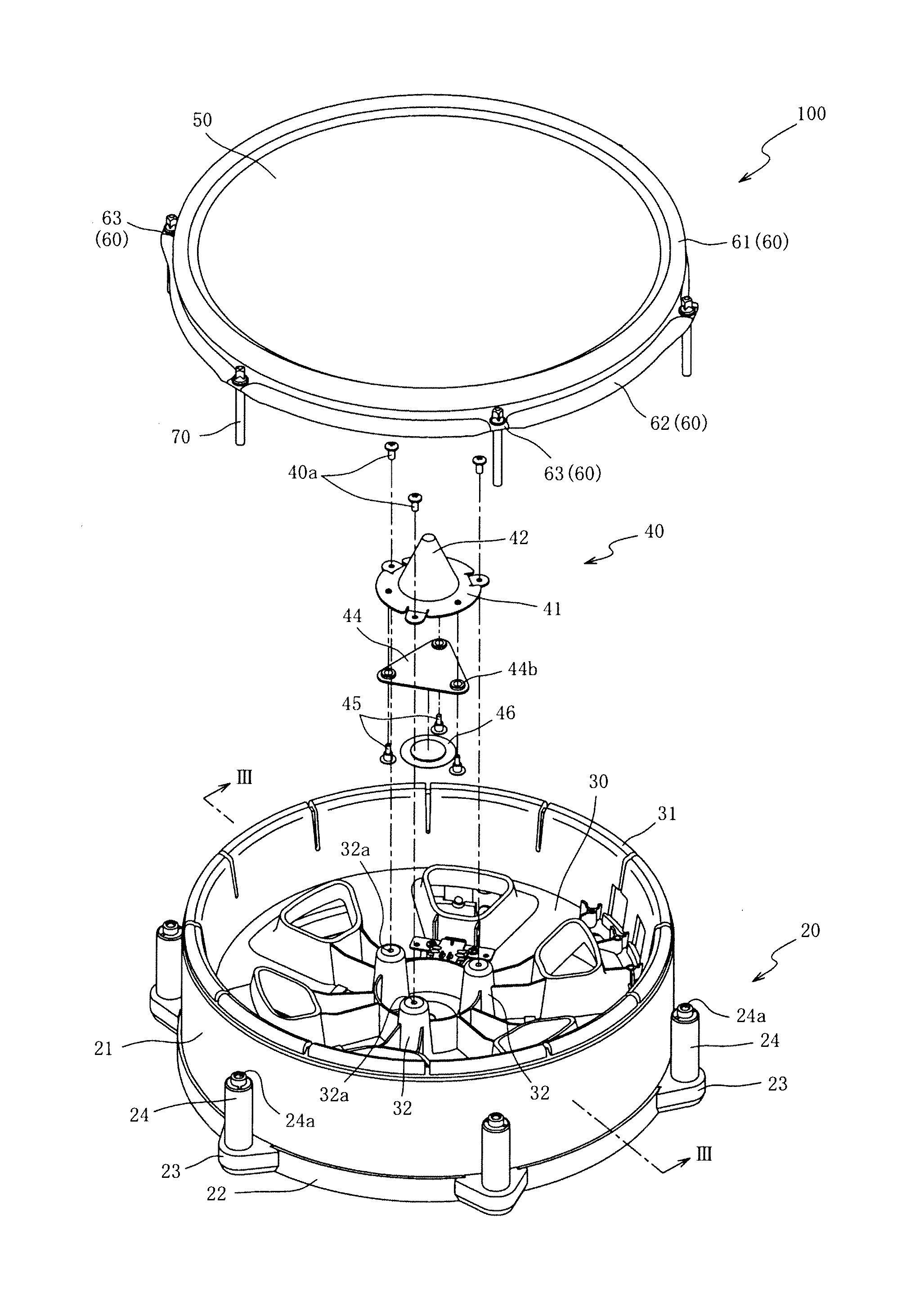
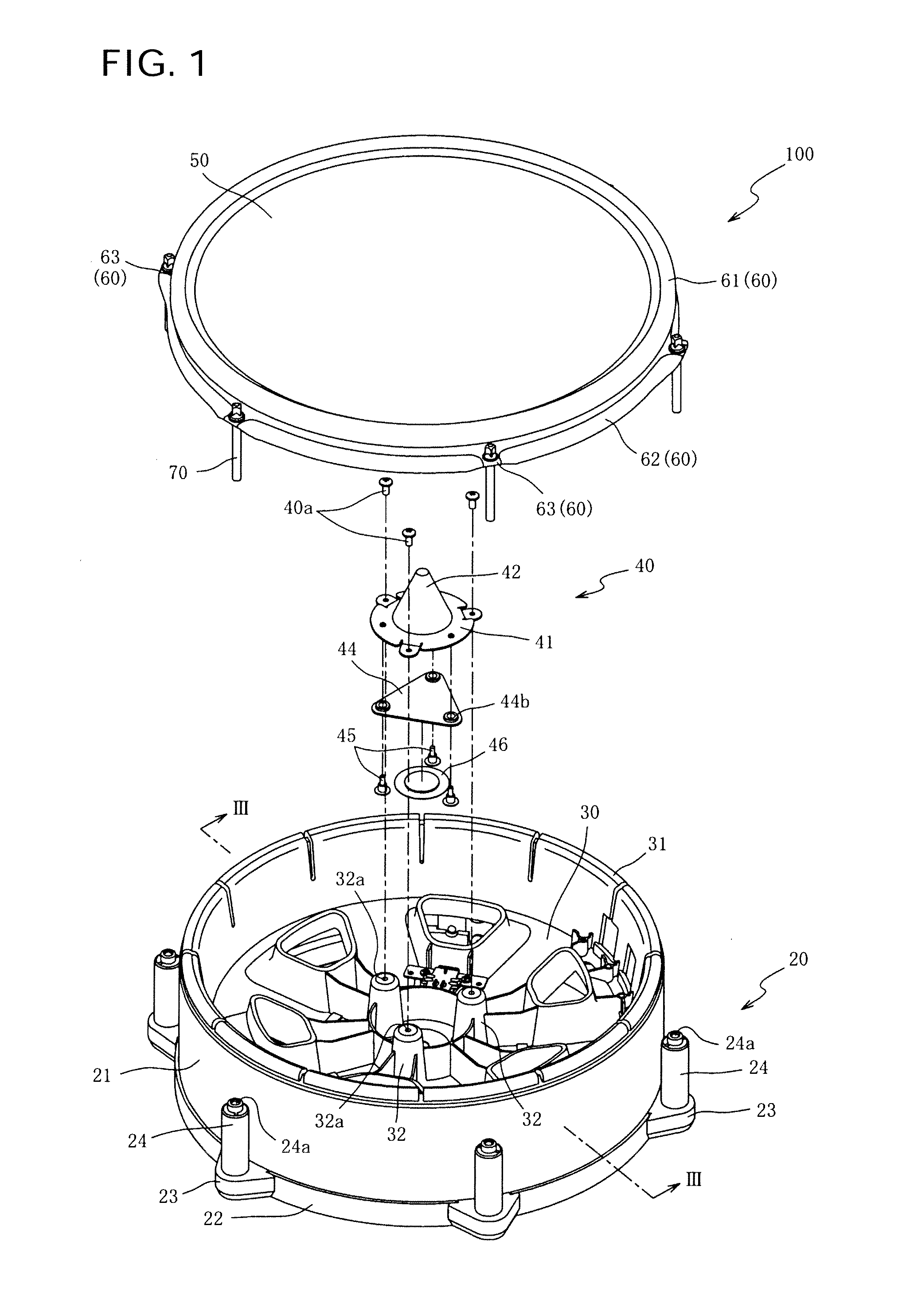
[0029]Embodiments of the invention are described below with reference to the accompanying drawings. An example of an electronic percussion instrument 100 according to an embodiment of the present invention is shown FIG. 1.

[0030]The electronic percussion instrument 100 is a percussion instrument that may be performed using sticks or the like. The electronic percussion instrument 100 is provided with a main body 20, a frame 30, a sensor section 40, a head 50, a rim section 60 and bolts 70. The main body 20 is open on one side (the top side in FIG. 1). The frame 30 is arranged over the open side of the main body 20 and extends into the main body 20. The sensor section 40 is attached to the frame 30. The head 50 is supported in contact with the sensor section 40. The rim section 60 is retained at the outer circumferential portion of the head 50. The bolts 70 affix the rim section 60 to the main body 20.

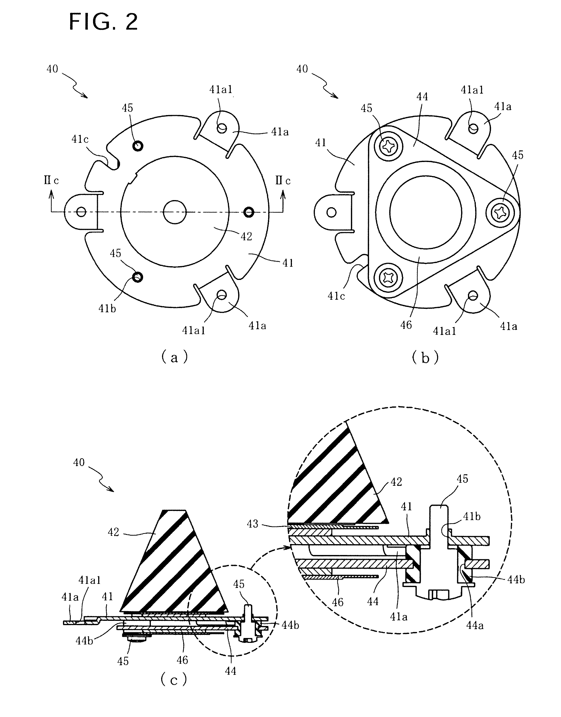
[0031]The sensor section 40 includes a head sensor 43 (see FIG. 2) and a rim sensor 4...


PUM

PropertyMeasurementUnit
frequencyaaaaaaaaaa
tensionaaaaaaaaaa
pressureaaaaaaaaaa

Abstract

A percussion instrument that suppresses erroneous detection by a rim sensor includes a first plate affixed to a frame, a second plate elastically supported on the first plate by one or more elastic members, and a rim sensor attached to the second plate. Large vibrations of the frame from an impact of a strike on the rim are transmitted to the second plate, and the rim sensor provides an output corresponding to the striking force. Also, vibrations of the frame generated by striking sound or external sound is attenuated by the elastic member, to suppress transmission of such vibrations to the second plate.

Description

CROSS-REFERENCE TO RELATED PATENT APPLICATIONS[0001]Japan Priority Application No. 2012-004368, filed on Jan. 12, 2012, including the specification, drawings, claims and abstract, is incorporated herein by reference in its entirety.FIELD OF THE INVENTION[0002]Embodiments of the present invention relate, generally, to percussion instruments, components of percussion instruments, processes of making and using such percussion instruments and systems employing such percussion instruments. Particular embodiments of the invention relate to percussion instrument systems, apparatuses and processes that employ a structure that is capable of suppressing erroneous detection of vibrations by a rim sensor.BACKGROUND[0003]Attempts have been made to configure an electronic percussion instrument in a manner to simulate an acoustic percussion instrument. For example, Japanese Laid-open Patent Application 2004-198657 describes an electronic percussion instrument 1 that includes a head 5, a rim 6, a s...

Claims


Application Information

Patent Timeline
Patent Type & Authority Applications(United States)
IPC IPC(8): G10H3/00B23P17/04
CPCG10H3/14Y10T29/49574G10H3/146G10H2230/301G10H2230/275
Inventor MORI, YOSHIAKI
Owner ROLAND CORP
Learn More