Change region detection device and change region detecting method

a detection device and change region technology, applied in the direction of instruments, television systems, color signal processing circuits, etc., can solve the problems of inaccurate detection, inability to perform accurate detection, and inability to detect the whole brightness change attributed to the illumination change, so as to suppress the erroneous detection of the change region and prevent the omission of detection

Inactive Publication Date: 2010-07-13
KK TOSHIBA
View PDF1 Cites 8 Cited by
  • Summary
  • Abstract
  • Description
  • Claims
  • Application Information

AI Technical Summary

Benefits of technology

[0012]The present invention can prevent the omission of detection by suppressing the erroneous detection of the change region.

Problems solved by technology

However, the background differential method which constitutes the first method has a drawback that the whole brightness change attributed to the illumination change is erroneously detected as the change attributed to a figure or the like.
The texture differential method which constitutes the second method may sufficiently cope with the change of brightness and may perform a small number of erroneous detections but has a drawback that the accurate detection cannot be performed when neither a background nor a figure or the like has texture.
The third method determines the change range based on the increase or decrease of the edge and hence, the method has a drawback that the accurate detection cannot be performed when neither a background nor an invading object or the like has texture.

Method used


Image

  • Change region detection device and change region detecting method
  • Change region detection device and change region detecting method
  • Change region detection device and change region detecting method

Examples


first embodiment

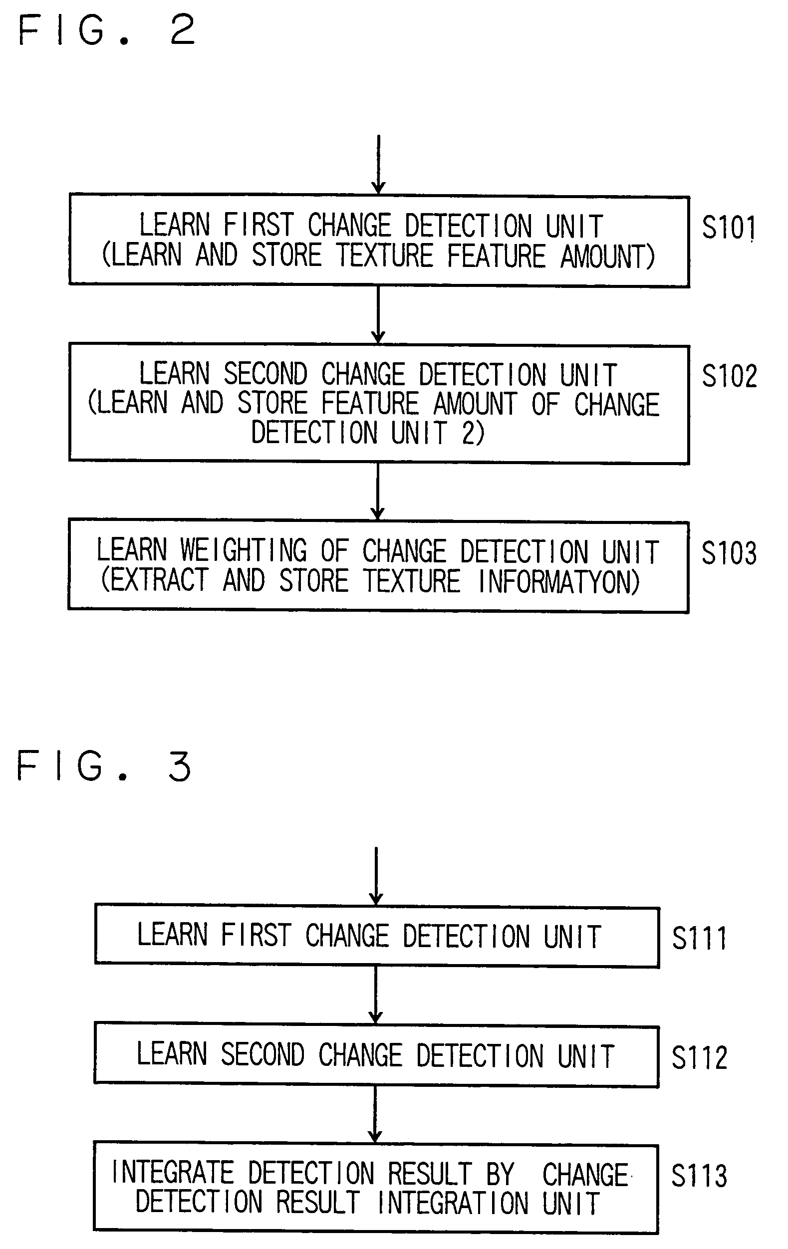
[0029]A change region detection device of a first embodiment according to the present invention is explained in conjunction with FIG. 1 to FIG. 8.

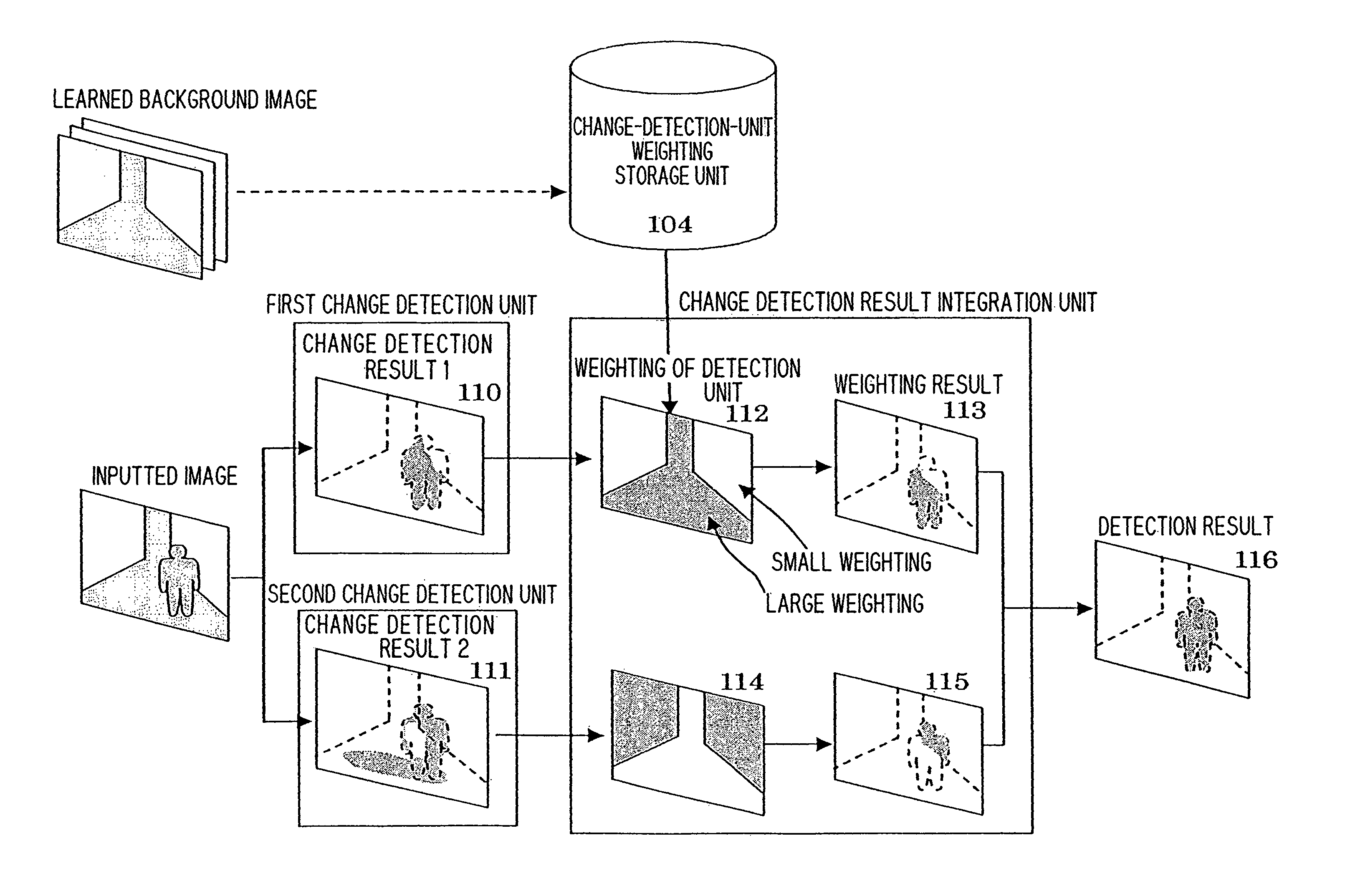
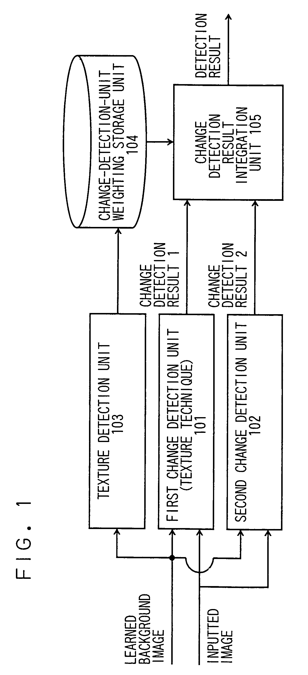
[0030]FIG. 1 is a block diagram showing the whole constitution of the change region detection device according to this embodiment, FIG. 2 is a schematic view showing a flow of learning processing, FIG. 3 is a schematic view showing a flow of detection processing, and FIG. 4 is a schematic view showing this embodiment.

(1) The Constitution of the Change Region Detection Device

[0031]The change region detection device shown in FIG. 1 includes a first change detection unit 101 which detects a change region based on texture information, a second change detection unit 102 which detects the change region based on a background differential method, a texture detecting unit 103, a change-detection-unit weighting storage unit (hereinafter, simply referred to as a storage unit) 104 and a change detection result integration unit (hereinafter, referred t...

second embodiment

[0078]A change region detection device of a second embodiment is explained in conjunction with FIG. 9 and FIG. 10.

[0079]FIG. 9 is a block diagram showing the whole constitution of this embodiment. The change region detection device shown in FIG. 9 includes a first change detection unit 201 which detects the change based on texture information, a second change detection unit 202, a texture removal unit 203, a storage unit 204, and an integration unit 205.

(1) Learning Processing

[0080]The learning processing of this embodiment is substantially equal to the learning processing of the first embodiment shown in FIG. 2 but differs from the learning processing of the first embodiment with respect to the learning processing on weighting in step S103. FIG. 10 shows a flow of the learning processing.

[0081]Steps S201, S202 shown in FIG. 10 are substantially equal to the steps S101, S102 shown in FIG. 2.

[0082]Next, in step S203, the texture removal unit 203 removes the texture from the learned b...

third embodiment

[0087]A change detection device of a third embodiment is explained in conjunction with FIG. 11 to FIG. 13.

[0088]FIG. 11 is a block diagram showing the whole constitution of this embodiment. The change region detection device shown in FIG. 11 includes a first change detection unit 301 which detects the change based on texture information, a second change detection unit 302 which detects the change based on texture information extracted from a region wider than the first change detection unit 301, a texture removal unit 303, a storage unit 304, and an integration unit 305.

[0089]Although the third embodiment has substantially the same constitution as the second embodiment shown in FIG. 9, this embodiment differs from the second embodiment with respect to a point that as the change detection unit, a change detection unit which detects the change based on the texture information extracted from the wide region is used. Accordingly, the explanation is made by focusing on portions which dif...


PUM


Abstract

A device includes a first change detection unit which detects a change region distribution based on the texture information; a second change detection unit which detects a change region distribution based on a background differential method; a texture detection unit, a change-detection-unit weighting storage unit, and a change detection result integration unit, wherein while applying a firm texture differential method to the illumination change as much as possible, a detection unit based on a background differential method is applied to a region to which the texture differential method is not favorably applicable.

Description

CROSS-REFERENCE TO RELATED APPLICATIONS[0001]This application is based upon and claims the benefit of priority from the prior Japanese Patent Application No. 2005-348530, filed on Dec. 1, 2005; the entire contents of which are incorporated herein by reference.TECHNICAL FIELD[0002]The present invention relates to a change region detection device and a change region detecting method on an image processing technique for extracting a region in which abnormality or change is generated by comparing a learned image in a normal situation and a present inputted image.BACKGROUND OF THE INVENTION[0003]As conventional change region detecting methods, following methods may be named.[0004]The first method is a background differential method in which a change region is detected based on the brightness difference between a learned average background image and an inputted image (Kentaro Toyama, John Krumm, Barry Brumitt, and Brian Meyers. Wallflower: Principles and practice of background maintenance...

Claims


Application Information

Patent Timeline
Patent Type & Authority Patents(United States)
IPC IPC(8): G06K9/00G06K9/62G06K9/46H04N5/14H04N9/64
CPCG06V20/52
Inventor YOKOI, KENTARO
Owner KK TOSHIBA
Why Eureka
Try Eureka