Base plate processing device

A substrate processing device and substrate technology, applied to measuring devices, optical devices, and devices for coating liquid on the surface, etc., can solve problems such as poor coating, damage to slit nozzles, and attenuation of light received by lasers, and achieve suppression of errors. Effects of detection, accuracy improvement, and burden reduction

Active Publication Date: 2006-03-01
DAINIPPON SCREEN MTG CO LTD
View PDF1 Cites 8 Cited by
  • Summary
  • Abstract
  • Description
  • Claims
  • Application Information

AI Technical Summary

Problems solved by technology

[0004] (1) Damage to the slit nozzle;
[0005] (2) There are cracks in the substrate, or the substrate is damaged;
[0006] (3) Coating while dragging foreign matter, which may cause poor coating, etc.
However, in the conventional device, the light projecting unit 101 and the light receiving unit 102 are shifted due to vibration during movement, and the received light amount of the laser beam may be attenuated accordingly.
That is, in conventional devices, there is a problem that if the sensitivity is increased, false detection will occur.

Method used


Image

  • Base plate processing device
  • Base plate processing device
  • Base plate processing device

Examples


Embodiment Construction

[0042] Hereinafter, preferred embodiments of the present invention will be described in detail with reference to the drawings.

[0043] 1. The first embodiment

[0044] 1.1 Description of composition

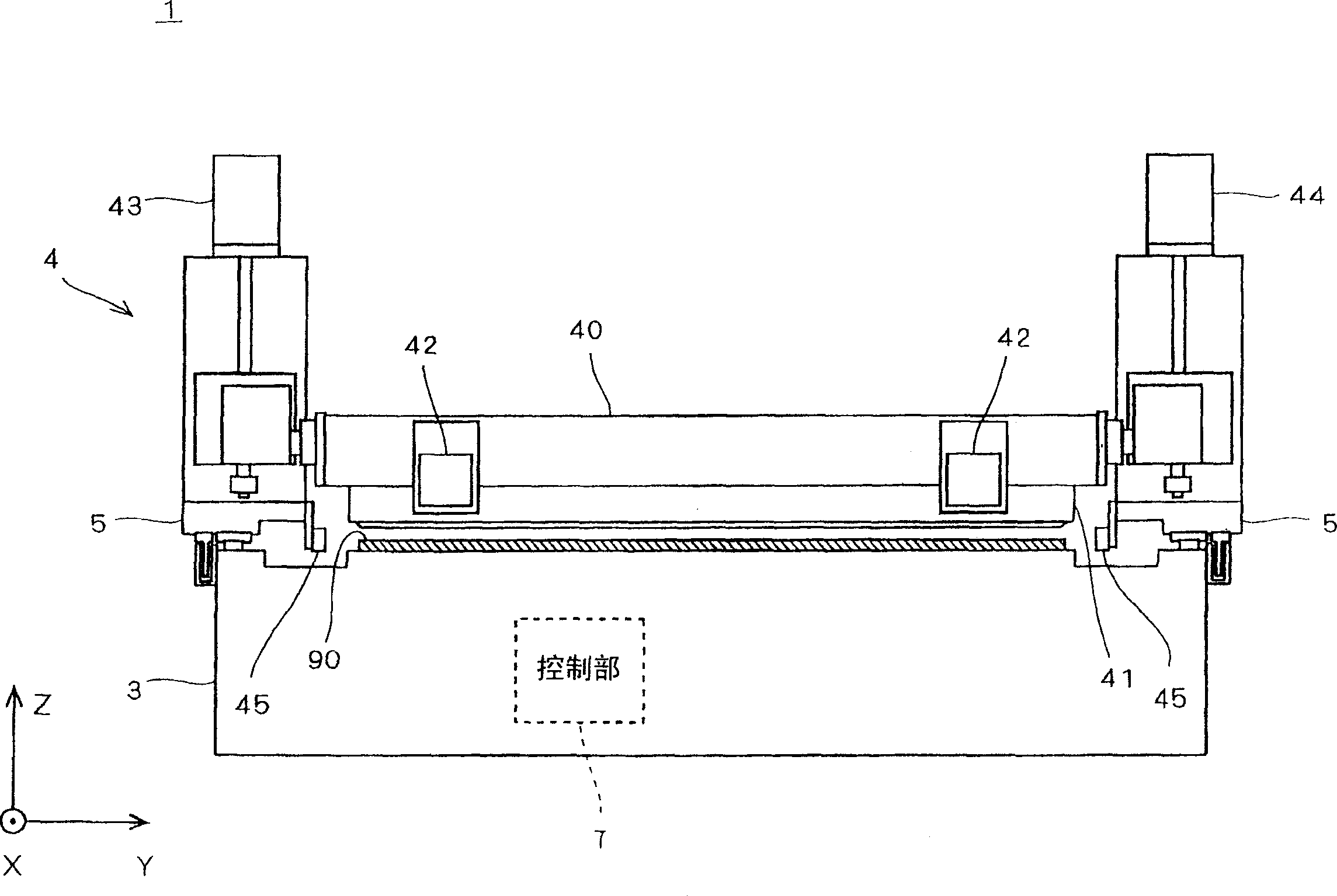
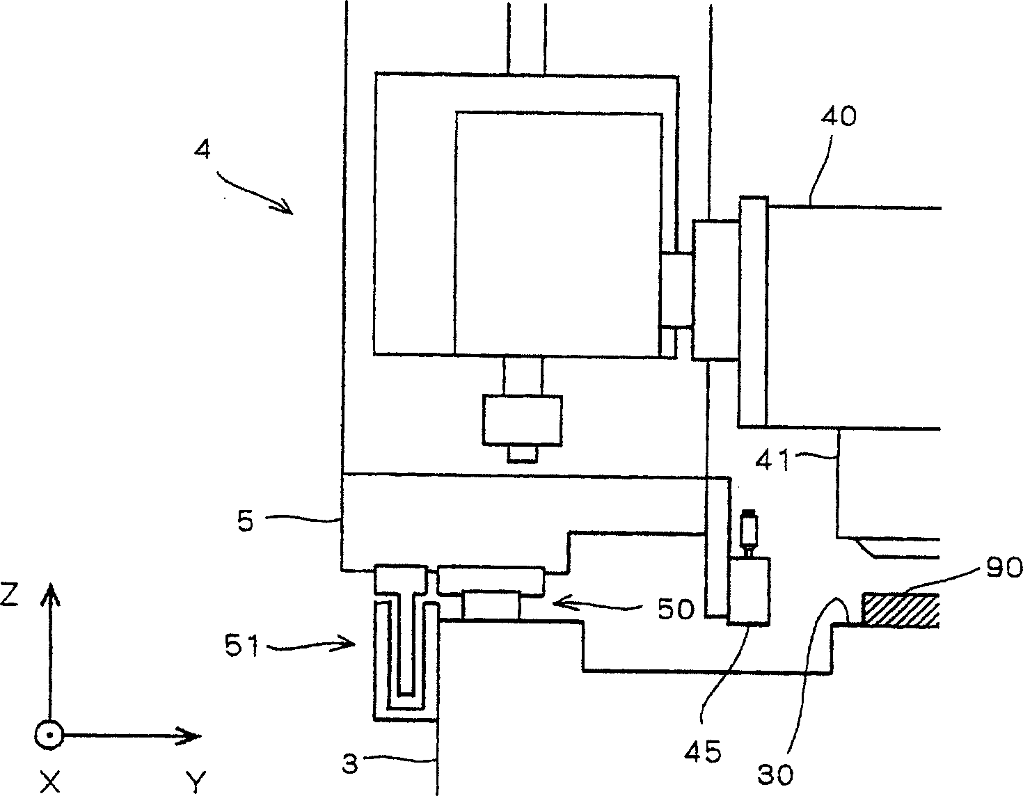
[0045] figure 1 is a front view of the substrate processing apparatus 1 according to the first embodiment of the present invention, figure 2 It is an enlarged view of the peripheral portion of the detection unit 45 in the substrate processing apparatus 1 . In addition, in figure 1 and figure 2 In the diagram, for the convenience of illustration and description, the Z-axis direction represents the vertical direction, and the XY plane represents the horizontal plane. This is defined for the convenience of grasping the positional relationship, and does not limit the directions described below. The same applies to subsequent figures.

[0046] The substrate processing apparatus 1 is used as the substrate 90 in the process of selectively etching the electrode layer etc. form...


PUM


Abstract

To reduce the load on workers while preventing lowering of the precision of the detection of an object. A substrate processing apparatus is provided with a light projecting part 450a and a light receiving part 450b which constitute a detection sensor 450. The light receiving part 450b is shifted in the (+Z) direction from a position where laser beam emitted from the light projecting part 450a is received and arranged at a position where the reflection light reflected by the object is received. In the substrate processing apparatus, when the light receiving part 450b receives the laser beam, it is judged that the object is existed and a movement mechanism of a slit nozzle is controlled.

Description

technical field [0001] The present invention relates to a technique of a substrate processing apparatus that applies a processing liquid to a surface of a substrate by scanning the substrate while ejecting the processing liquid from a nozzle. More specifically, it relates to a technique for detecting a target object with high accuracy in order to prevent the nozzle from interfering with a foreign object (object) during scanning using a nozzle. Background technique [0002] In the manufacturing process of glass square substrates for liquid crystals, semiconductor wafers, flexible substrates for thin-film liquid crystals, substrates for photomasks, substrates for color filters (hereinafter simply referred to as "substrates"), etc., the process of applying a treatment liquid to the surface of the substrate is used. Coating equipment (substrate processing equipment). As a coating device, there are known a slit coater that performs slit coating using a slit nozzle having a slit-...

Claims


Application Information

Patent Timeline
Patent Type & Authority Applications(China)
IPC IPC(8): B05C5/02B05C13/00G01D3/08
CPCB05C5/0225B05C11/00B05C13/00G01B11/00
Inventor 西冈贤太郎高木善则
Owner DAINIPPON SCREEN MTG CO LTD
Why Eureka
Try Eureka