
Stick-slip detecting device and detecting method

A detection device and detection method technology, applied in the direction of measuring device, valve device, mechanical device, etc., can solve the problems of stick-slip false detection, inhibit stick-slip false detection, etc., and achieve the effect of inhibiting false detection

Active Publication Date: 2013-05-15
YAMATAKE HONEYWELL CO LTD
View PDF7 Cites 9 Cited by
  • Summary
  • Abstract
  • Description
  • Claims
  • Application Information

AI Technical Summary

Problems solved by technology

[0025] In this way, in the technique disclosed in Patent Document 2, false detection of stick-slip may occur in some cases, and it cannot be said that false detection of stick-slip can be suppressed with high precision.

Method used


Image

  • Stick-slip detecting device and detecting method
  • Stick-slip detecting device and detecting method
  • Stick-slip detecting device and detecting method

Examples


Embodiment Construction

[0048] Hereinafter, embodiments of the present invention will be described in detail with reference to the drawings.

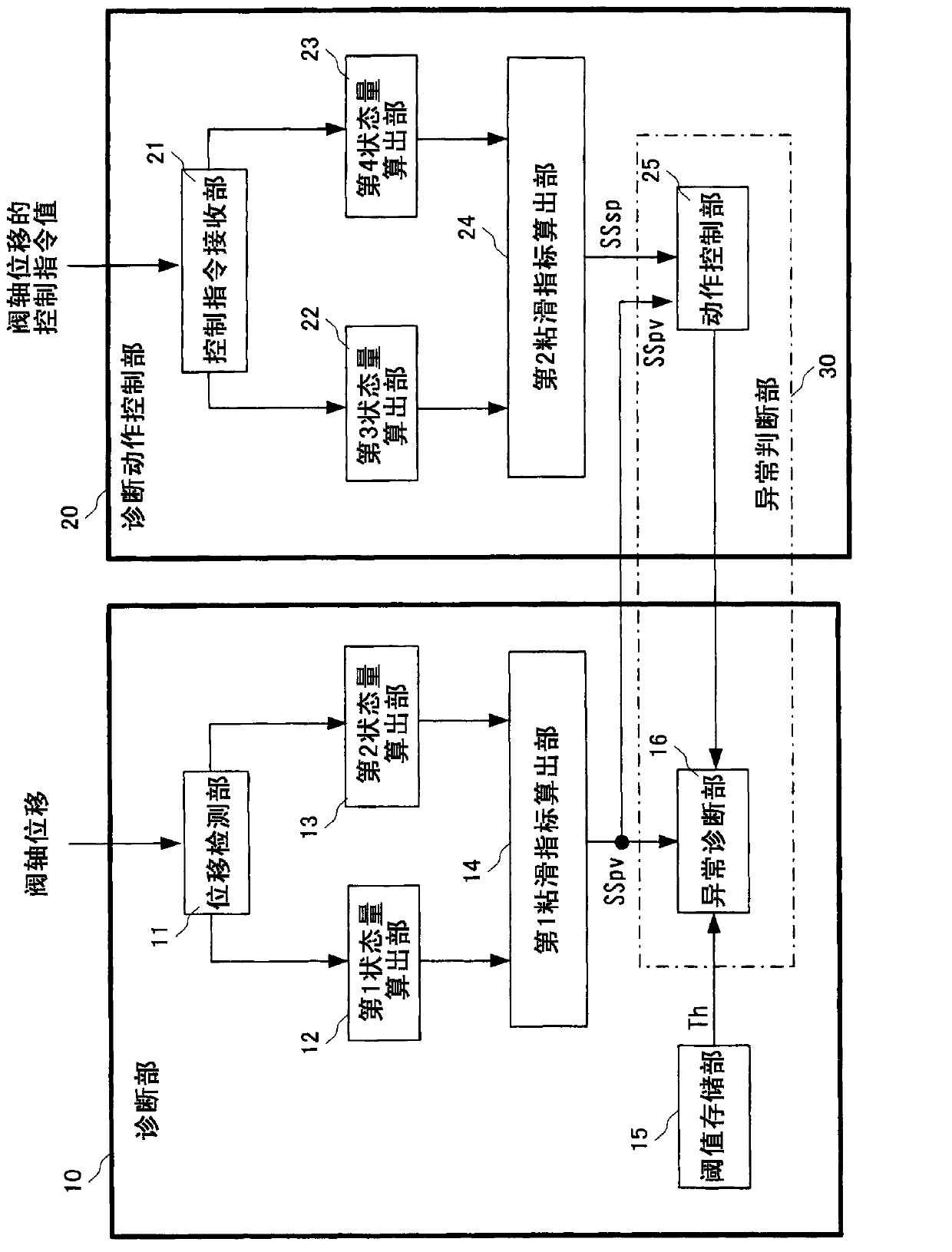
[0049] figure 1 It is a figure which shows the main part of one embodiment of the stick-slip detection apparatus of this invention. This stick-slip detection device includes: a diagnosis unit 10 for diagnosing an abnormality based on the displacement of a movable part having a contact-sliding part; Diagnose the motion control unit 20 .

[0050] In this embodiment, the displacement of the movable part with the contact sliding part is defined as the valve shaft displacement of the regulating valve whose opening degree is controlled by the positioner, and the control command value for controlling the displacement of the movable part is defined as the valve shaft displacement of the positioner. The control command value of displacement.

[0051] The diagnosis unit 10 includes a displacement detection unit 11 , a first state quantity calculation unit 12 , a sec...


PUM


Abstract

A first state quantity and a second state quantity of a valve stem dislocation are calculated, and a ratio of the first state quantity and the second state quantity is calculated as a first stick-slip indicator SSpv in a first stick-slip indicator calculating portion (14). A third state quantity and a fourth state quantity of a control instruction value of a valve stem dislocation are calculated, and a ratio of the third state quantity and the fourth state quantity is calculated as a second stick-slip indicator SSsp in a second stick-slip indicator calculating portion. With a threshold value as Th, a first constant as alpha, and a second constant as beta, a fault evaluating portion concludes that a stick-slip has occurred when the conditional expression''SSpv>Th AND SSpv>alphaSSsp+beta''is satisfied.

Description

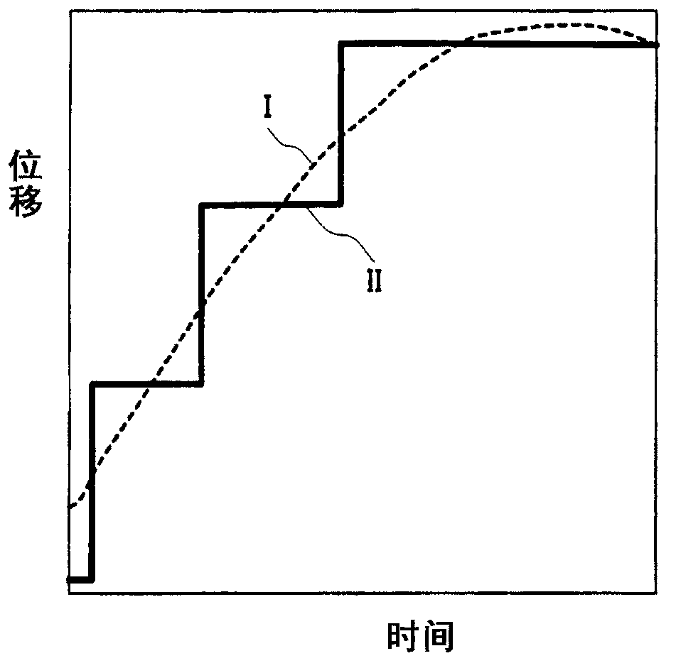
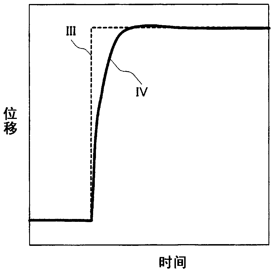
technical field [0001] The present invention relates to a stick-slip detection device and detection method for detecting stick-slip during operation of a device having a contact-sliding portion such as a regulator valve or a gas regulator. Background technique [0002] A malfunction of a regulating valve or a gas regulator can be diagnosed by detecting the occurrence of stick-slip in the contact sliding part. slimy, eg Figure 8 As shown in , it occurs due to the state of the contact sliding portion 103 between the piston 101 and the cylinder 102 . For example, this stick-slip occurs when foreign matter enters into contact with the sliding portion 103 or the like. Therefore, stick-slip detection can be performed by detecting the displacement of the piston 101 and monitoring the state of the detected displacement (see Patent Document 1). [0003] Here, the stick-slip detection described in Patent Document 1 will be briefly described. In this detection technology, the displ...

Claims


Application Information

Patent Timeline
Patent Type & Authority Applications(China)
IPC IPC(8): G01M13/00
CPCF16K37/0075G01N19/00F16K37/0041F16K37/0083
Inventor 鹿岛亨
Owner YAMATAKE HONEYWELL CO LTD
Learn More