Panel member control system

a control system and panel technology, applied in the direction of motor/generator/converter stopper, dynamo-electric converter control, instruments, etc., can solve the problems of vibration that lasts longer than the duration of time and is likely to be erroneously determined to be pinching, and achieves small pinch load, limit erroneous detection of pinching, and reduce the effect of vibration

Active Publication Date: 2009-06-02
DENSO CORP
View PDF11 Cites 10 Cited by
  • Summary
  • Abstract
  • Description
  • Claims
  • Application Information

AI Technical Summary

Benefits of technology

[0016]The present invention addresses the above disadvantages. Thus, it is an objective to provide a panel member control system, which can limit erroneous detection of pinching due to a relatively small normal disturbance that is caused while a vehicle is running and a relatively large disturbance that is caused while the vehicle is running on a rough road, and which can restrict a pinch load to a relatively small value.

Problems solved by technology

Accordingly, the power window device has a disadvantage that it operates reversely due to erroneous detection of the pinching during the course of closing the windowpane when the vehicle door is opened / closed or while the vehicle is running.
Nevertheless, in the windowpane control device in JP2002-96632A, if the period of duration, which is used for determining the pinching while the vehicle is running on the rough road, is set at a relatively large value, there is likely to be a period, during which the pinching cannot be detected immediately after the vehicle runs past the rough road.
Also, vibration that lasts longer than the period of duration is likely to be erroneously determined to be the pinching, if the period of duration is set at a relatively small value.
Moreover, there is a disadvantage that a load used for the reverse operation remains large for a while even after the vehicle resumes running on the normal road from the rough road, if the period, during which the pinching determination threshold for the rough road is continuously employed, is set at a relatively large value.
Hence, there is a disadvantage that the load used for the reverse operation needs to be set at a relatively large value in order to avoid an erroneous determination.

Method used


Image

  • Panel member control system
  • Panel member control system
  • Panel member control system

Examples


Embodiment Construction

[0034]With reference to drawings, an embodiment of the present invention will be described below. In addition, it is apparent that configurations, procedures and the like, which will be described below, do not by any means limit the present invention, and that they can be changed in various ways without departing from the scope of the present invention.

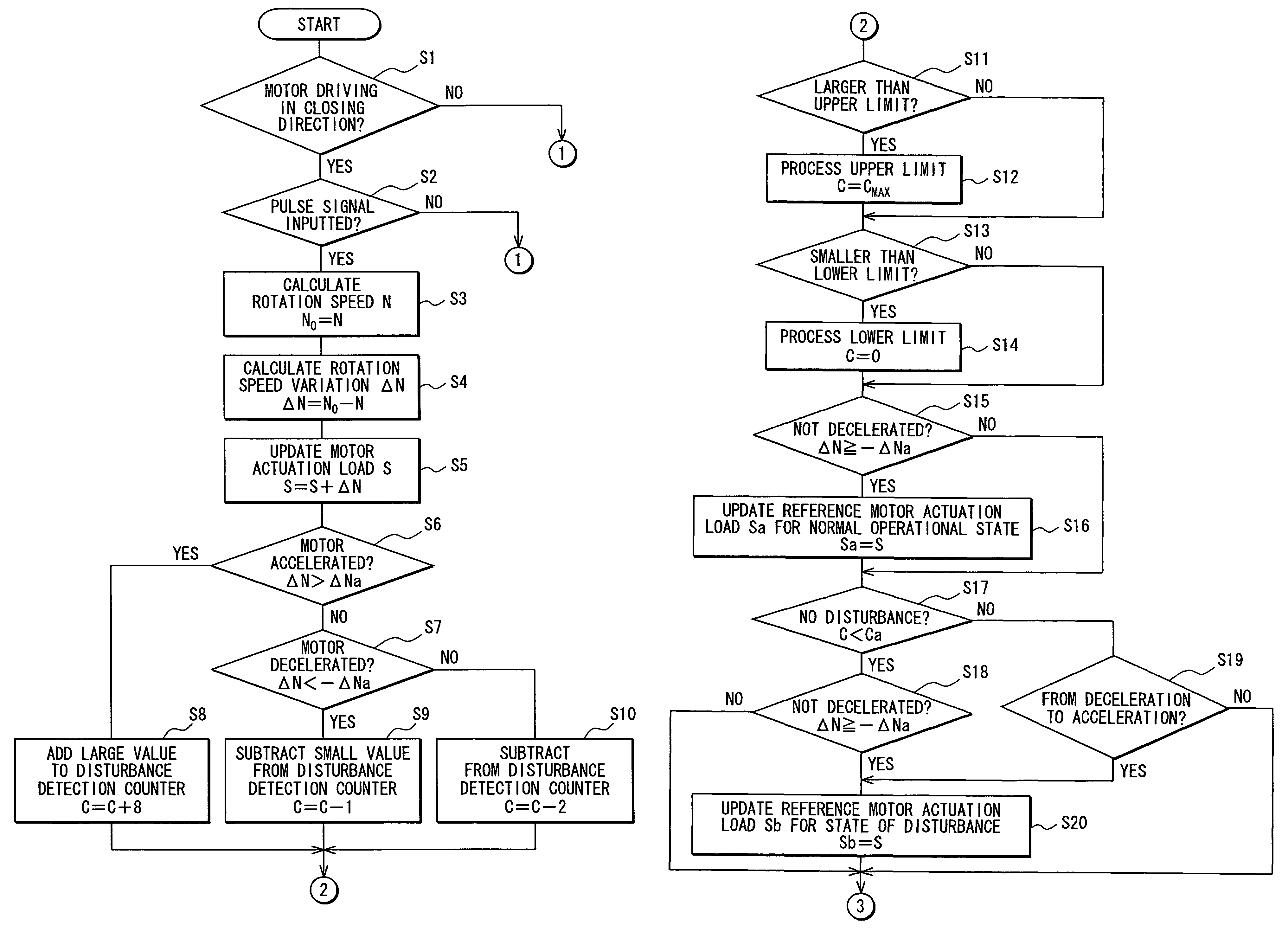
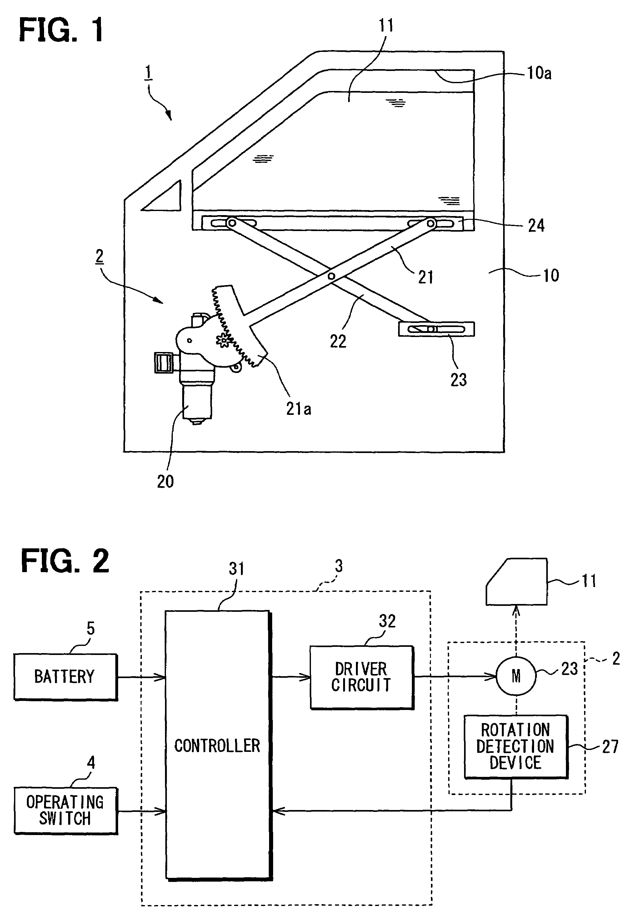
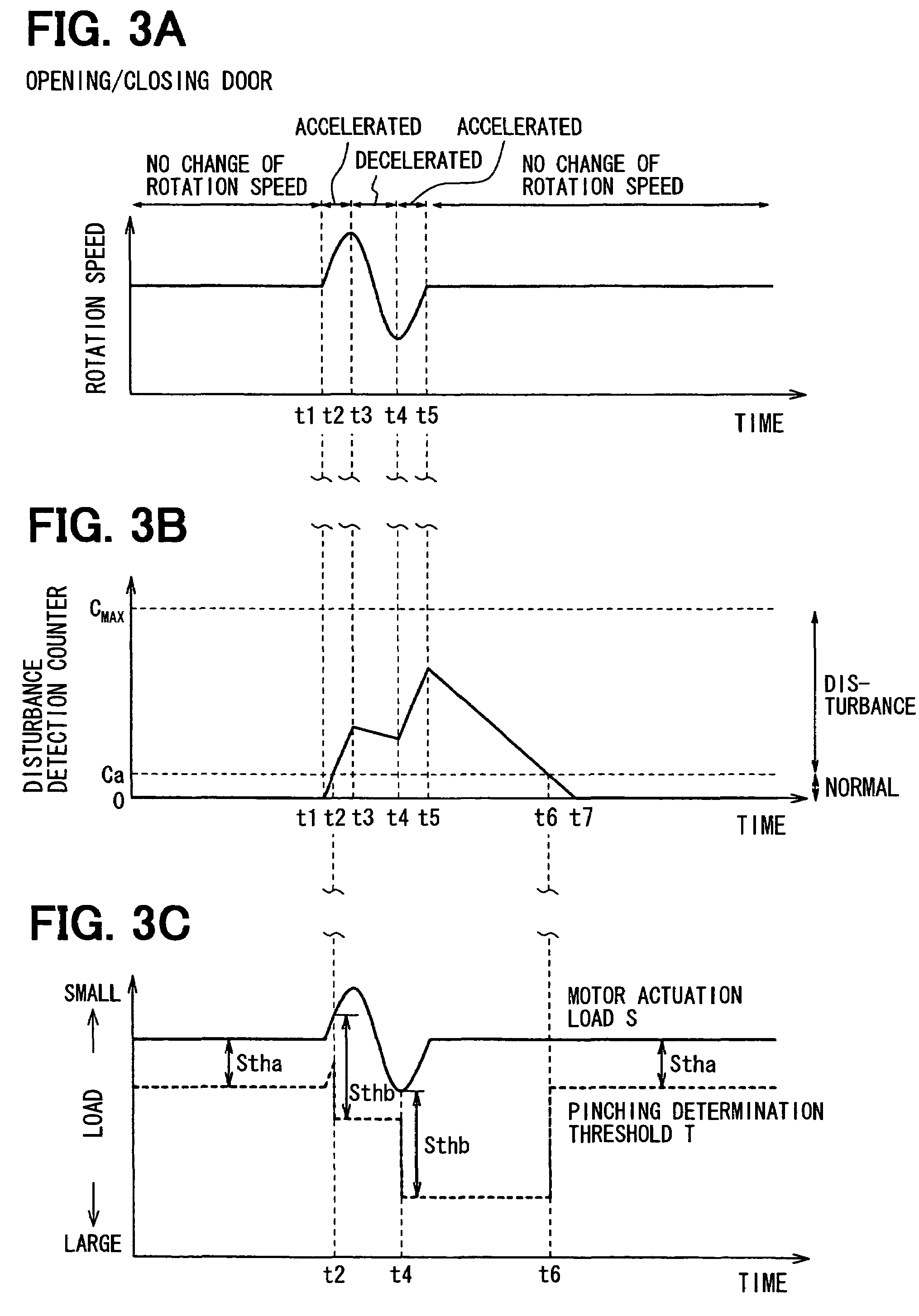
[0035]FIGS. 1 to 8 relate to the embodiment of the present invention. FIG. 1 is a schematic diagram illustrating a power window device. FIG. 2 is a block diagram of the power window device in FIG. 1. FIGS. 3A to 3C are diagrams illustrating pinching determination processing in opening / closing a door of a vehicle. FIGS. 4A to 4C are diagrams illustrating the pinching determination processing in running on a rough road. FIGS. 5A to 5C are diagrams illustrating the pinching determination processing when pinching is caused while the vehicle is running on the rough road. FIGS. 6 to 8 are flowcharts showing flows of the pinching determinati...


PUM


Abstract

A panel member control system for controlling a panel member includes a motor, a rotation detecting means, and a pinching detecting means. The rotation detecting means detects a rotational speed of the motor. The pinching detecting means detects an occurrence of pinching of an object by the panel member when a pinching indicative value exceeds a pinching determination threshold. The pinching detecting means includes a disturbance detecting means and a correcting means. The disturbance detecting means determines whether the motor is in a disturbed state based on a change in the rotational speed. The correcting means corrects the pinching determination threshold in view of a result of the determination made by the disturbance detecting means.

Description

CROSS REFERENCE TO RELATED APPLICATION[0001]This application is based on and incorporates herein by reference Japanese Patent Application No. 2005-327609 filed on Nov. 11, 2005.BACKGROUND OF THE INVENTION[0002]1. Field of the Invention[0003]The present invention relates to a panel member control system.[0004]2. Description of Related Art[0005]A device (e.g., a power window device and a sunroof device for a vehicle) for driving an opening / closing member to be opened / closed conventionally performs automatic reverse control on detecting pinching of a foreign object in the opening / closing member. In pinching detection processing of such a device, a variation (e.g., variations in a rotation speed of a drive motor, in a variability rate, and in a movement speed of the opening / closing member), which is caused by the pinching of the foreign object, is calculated. Then, it is determined that the pinching is produced when this variation exceeds a predetermined pinching determination threshold...

Claims


Application Information

Patent Timeline
Patent Type & Authority Patents(United States)
IPC IPC(8): E05F15/16
CPCH02H7/0851H02H1/04H02H7/093
Inventor HIRAI, KAZUYUKI
Owner DENSO CORP
Why Eureka
Try Eureka