
Downhole fluid separation system and method

Inactive Publication Date: 2013-07-18
BAKER HUGHES INC
View PDF6 Cites 5 Cited by
  • Summary
  • Abstract
  • Description
  • Claims
  • Application Information

AI Technical Summary

Benefits of technology

The patent describes a system and method for separating fluids from a mixture using a filter element. This filter element can be designed to preferentially attract the first component of the fluid mixture while impeding the flow of the other components. The method involves disposing the filter element in a downhole fluid mixture, modifying the difference in affinity between the first and second components, and then flowing the first component through the filter element while impeding the passage of the other components to separate them from the fluid mixture. The technical effects include efficient and effective separation of fluids from mixed flows.

Problems solved by technology

The separation of fluid components, e.g., gas from liquid components in a downhole fluid mixture is at times desired in the downhole drilling and completions industry.
Fluids can be separated from the fluid mixture once it has been produced, but this of course requires production of the entire fluid mixture, which is not always desired.
Some systems are known and utilized in the art for achieving downhole fluid separation, but are not tailorable to maximize efficiency of the fluid separation process with respect to particular downhole fluid mixtures (e.g., high water or oil content, etc.) or conditions (e.g., temperature, pressure, etc.).

Method used


Image

  • Downhole fluid separation system and method
  • Downhole fluid separation system and method
  • Downhole fluid separation system and method

Examples


Embodiment Construction

[0008]A detailed description of one or more embodiments of the disclosed apparatus and method are presented herein by way of exemplification and not limitation with reference to the Figures.

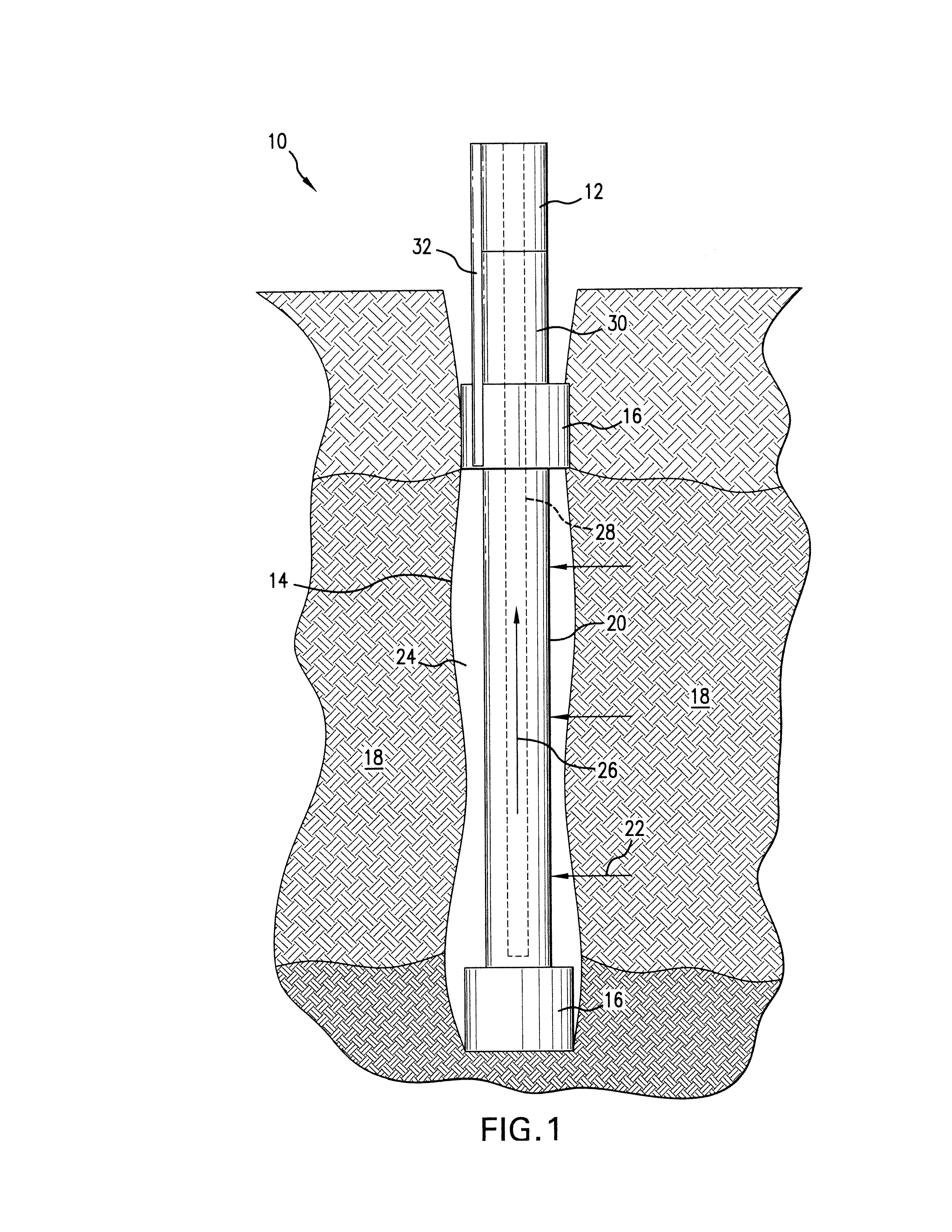
[0009]Referring now to FIG. 1, a fluid separation system 10 is illustrated. The system 10 includes, e.g., a string 12 run in a borehole 14. In the illustrated embodiment, the string 12 includes a pair of packers or other elements for sealing and / or isolating a zone 18 through which the borehole 14 is formed. The zone 18 is, for example, a production zone that contains a fluid mixture having at least one component that is desired for production. In one embodiment, the desired component is gaseous, e.g., natural gas.

[0010]In order to separate the desirable component from the other fluid components of the fluid mixture in the zone 18, the string 12 includes a filter element 20. The filter element 20 is arranged to preferentially enable the desirable component to flow therethrough while impeding the ...


PUM

PropertyMeasurementUnit
Hydrophobicityaaaaaaaaaa
Surface tensionaaaaaaaaaa
Poreaaaaaaaaaa

Abstract

A system for separating fluids of a fluid mixture including a filter element operatively arranged for enabling a first component of a fluid mixture to flow therethrough while impeding flow of at least one other fluid component of the fluid mixture. An additive is configured to improve a first affinity of the filter element for the first component relative to a second affinity of the filter element for the at least one other fluid component of the fluid mixture. A method of separating fluids is also included.

Description

BACKGROUND[0001]The separation of fluid components, e.g., gas from liquid components in a downhole fluid mixture is at times desired in the downhole drilling and completions industry. Fluids can be separated from the fluid mixture once it has been produced, but this of course requires production of the entire fluid mixture, which is not always desired. Some systems are known and utilized in the art for achieving downhole fluid separation, but are not tailorable to maximize efficiency of the fluid separation process with respect to particular downhole fluid mixtures (e.g., high water or oil content, etc.) or conditions (e.g., temperature, pressure, etc.). In view of the foregoing, the industry well receives advances and alternatives in downhole fluid separation technology.BRIEF DESCRIPTION[0002]A system for separating fluids of a fluid mixture including a filter element operatively arranged for enabling a first component of a fluid mixture to flow therethrough while impeding flow of ...

Claims


Application Information

Patent Timeline
IPC IPC(8): B01D19/00B82Y30/00
CPCE21B43/082E21B43/12B01D19/0031B82Y30/00E21B43/38
Inventor REN, JIAXIANGGERRARD, DAVID P.WELCH, JOHN C.GOODSON, JAMES E.
Owner BAKER HUGHES INC
Learn More