
Machine having an air bearing and method for operating such a machine

Active Publication Date: 2013-07-18
CARL ZEISS IND MESSTECHN GMBH
View PDF14 Cites 5 Cited by
  • Summary
  • Abstract
  • Description
  • Claims
  • Application Information

AI Technical Summary

Benefits of technology

The patent is about a machine and a way to operate it that makes it easy and reliable to use while saving money on compressed air. The technical effect of this invention is that it provides a more efficient and effective way to use machines while saving energy.

Problems solved by technology

This would happen if the air bearings are insufficiently supplied with compressed air and the head is displaced.
In this case, the parts to be supported with respect to one another rest on one another, so that friction occurs between the parts.
If the head is displaced in this situation, this leads to damage between the parts owing to the friction.
It can also cause damage to the actuators, which may be overloaded because of the friction.
In the event of long static times, the disadvantage arises that the measuring devices are contaminated by the compressed air.
Switching off the machine completely during static times has the disadvantage that the machine has to be switched on again for renewed operation.
First, the air bearings have to be supplied sufficiently with compressed air.
Such initialization steps require time, which increases the static time of the machine and thereby reduces the availability of the machine.
Automatic restart of the machine is not possible then, so that a user has to restart the machine manually and carry out the initialization steps mentioned above.
This can cause position lags, which lead to measurement errors or defective workpieces.

Method used


Image

  • Machine having an air bearing and method for operating such a machine
  • Machine having an air bearing and method for operating such a machine
  • Machine having an air bearing and method for operating such a machine

Examples


Embodiment Construction

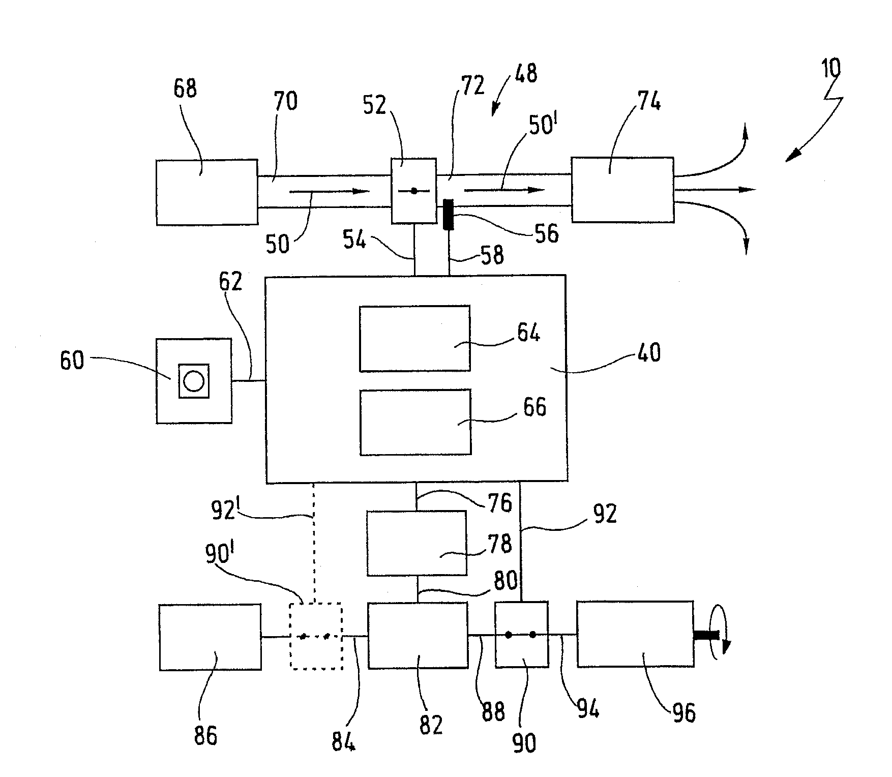
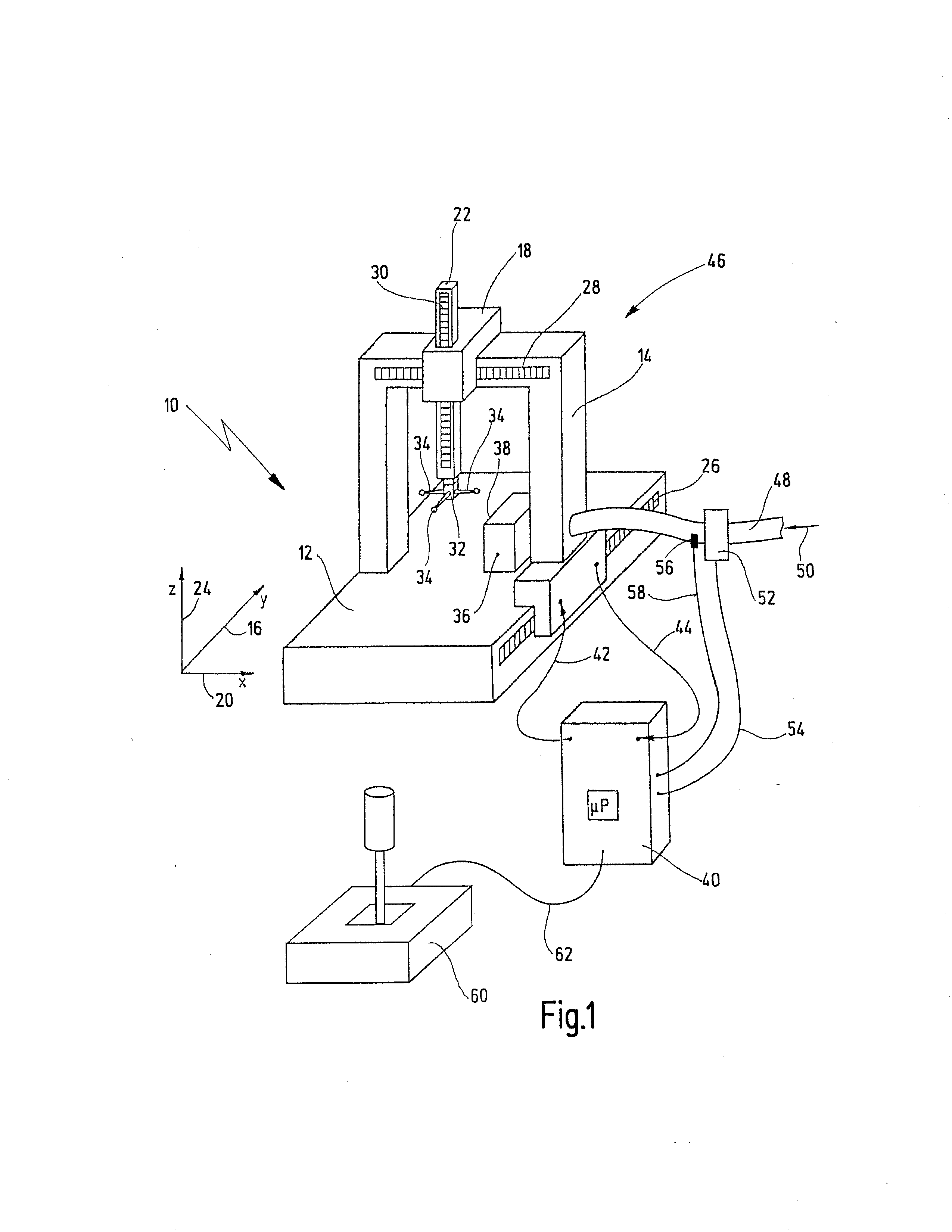
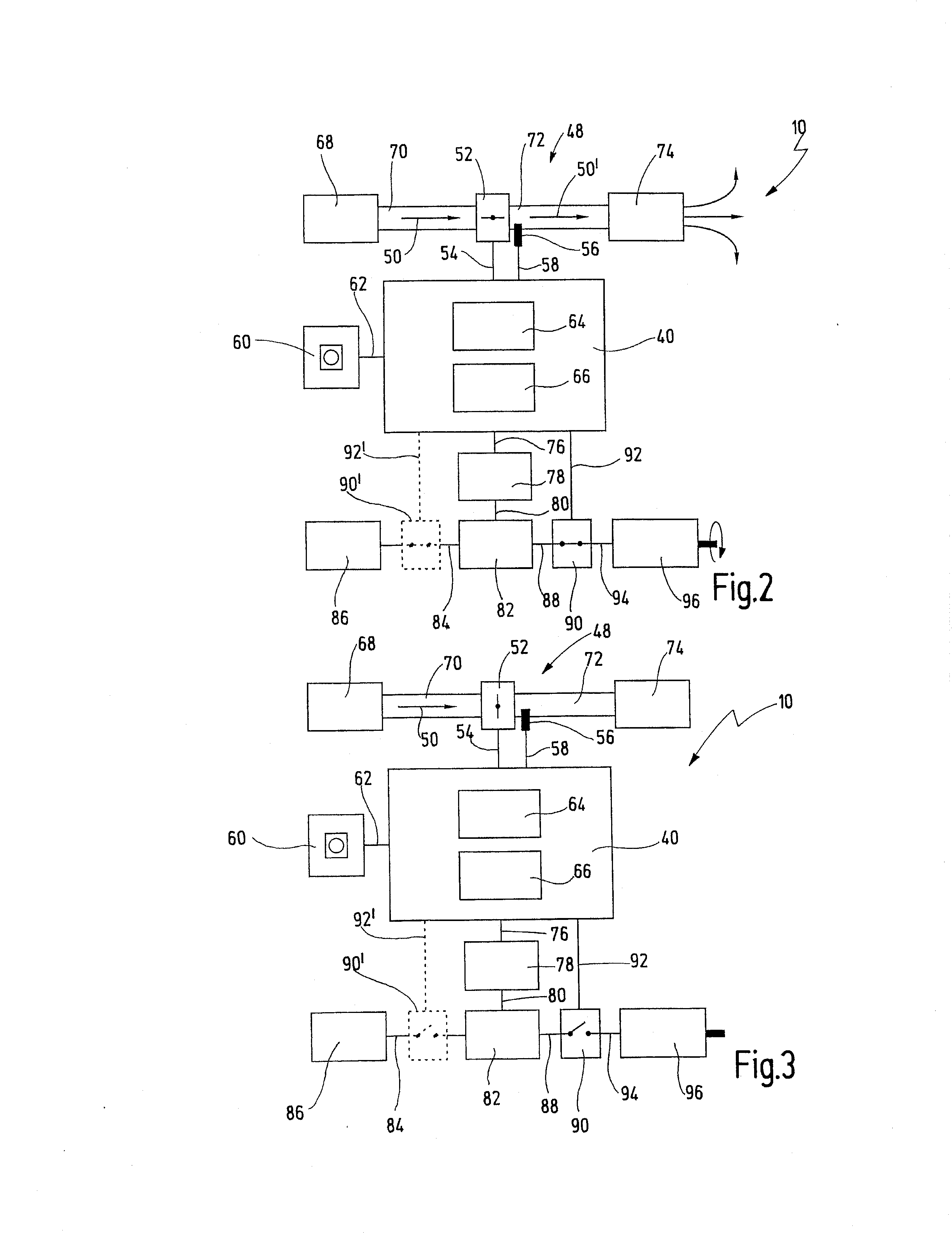
[0053]In FIG. 1, a coordinate measuring machine is denoted in its entirety by reference number 10. The coordinate measuring machine 10 is represented here by way of example in gantry design. The invention is not, however, restricted to a particular frame structure and may also be used for coordinate measuring machines in another design. The coordinate measuring machine 10 serves here as an exemplary embodiment of a machine according to the invention. The invention is also not restricted to coordinate measuring machines, but may for example also be used for machine tools and other machines comprising air-supported parts.

[0054]The coordinate measuring machine comprises a base 12, on which a gantry 14 is arranged. The gantry 14 can be displaced with the aid of an electrical drive (not represented here) along a spatial direction 16, which is usually referred to as the y axis. On the upper crossbar of the gantry 14, a carriage 18 is arranged which can be displaced in a second spatial dir...


PUM


Abstract

A machine has a frame structure for moving a machine head in one or more spatial directions. The frame structure comprises an actuator and an air bearing for moving the head. The machine also comprises a compressed air feed connected to the air bearing for providing a compressed air flow. A restrictor defines the compressed air flow to the air bearing. The machine has a first operating state, in which a high compressed air flow is defined and in which the actuator can be actuated. The machine has a second operating state, in which a compressed air flow lower than the high compressed air flow is defined. In the second operating state, the actuator is secured against actuation from a closed-loop position controller, while the closed-loop position controller is maintained in operation.

Description

CROSSREFERENCES TO RELATED APPLICATIONS[0001]This application is a continuation of international patent application PCT / EP2011 / 050832 filed on Jan. 21, 2011 designating the U.S., which international patent application has been published in German language and claims priority from German patent application DE 10 2010 006 297.9 filed on Jan. 21, 2010. The entire contents of these priority applications are incorporated herein by reference.BACKGROUND OF THE INVENTION[0002]The present invention relates to a machine having a moveable machine part and an air bearing supporting the moveable machine part. Moreover, the invention relates to an advantageous method for operating such a machine.[0003]Many machines, in particular machine tools and coordinate measuring machines, have a displaceable working head. In the case of a coordinate measuring machine, on which the following will be based by way of example, the head is often arranged on the lower free end of a vertically arranged quill. The ...

Claims


Application Information

Patent Timeline
IPC IPC(8): B23Q1/38
CPCB23Q1/38
Inventor STUMPP, ERNST
Owner CARL ZEISS IND MESSTECHN GMBH
Learn More