Turbine type gas magnetic engine

An engine and turbine-type technology, applied in the field of turbo-type aeromagnetic motors, can solve the problems of low output power, low efficiency, and large gas consumption, and achieve the effect of reducing compressed air

Inactive Publication Date: 2014-02-12
BEIHANG UNIV
View PDF0 Cites 2 Cited by
  • Summary
  • Abstract
  • Description
  • Claims
  • Application Information

AI Technical Summary

Problems solved by technology

[0003] However, the pneumatic engine also has obvious disadvantages,

Method used


Image

  • Turbine type gas magnetic engine
  • Turbine type gas magnetic engine
  • Turbine type gas magnetic engine

Examples


Embodiment Construction

[0015] The present invention will be further described below.

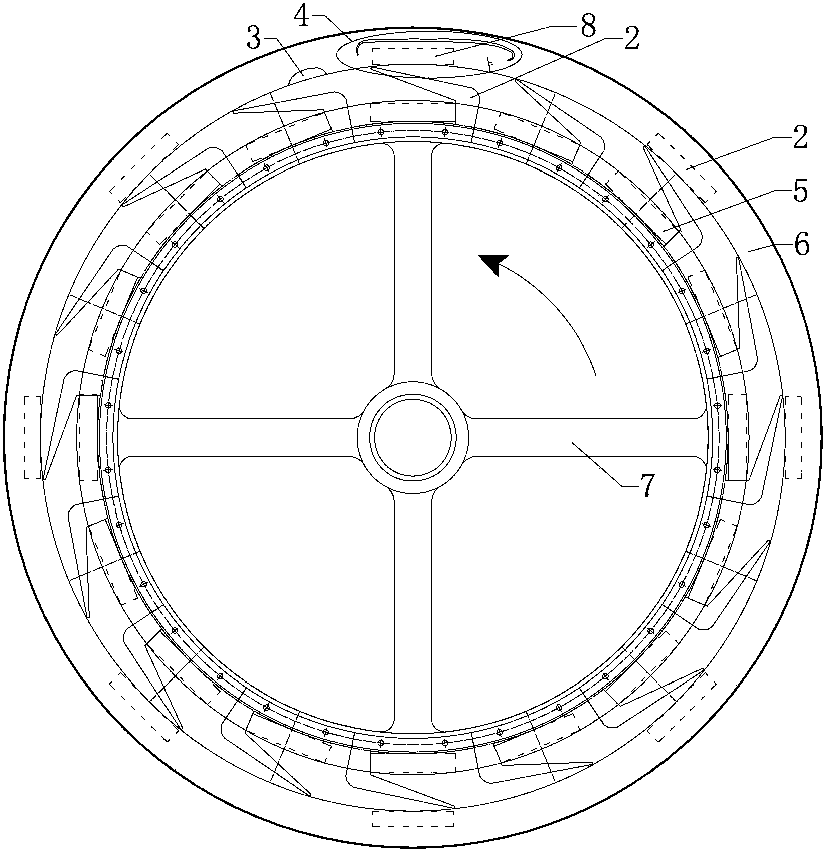
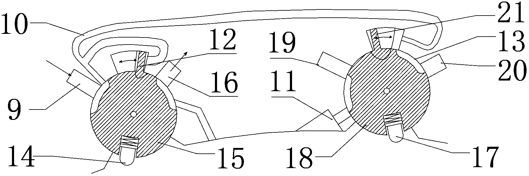
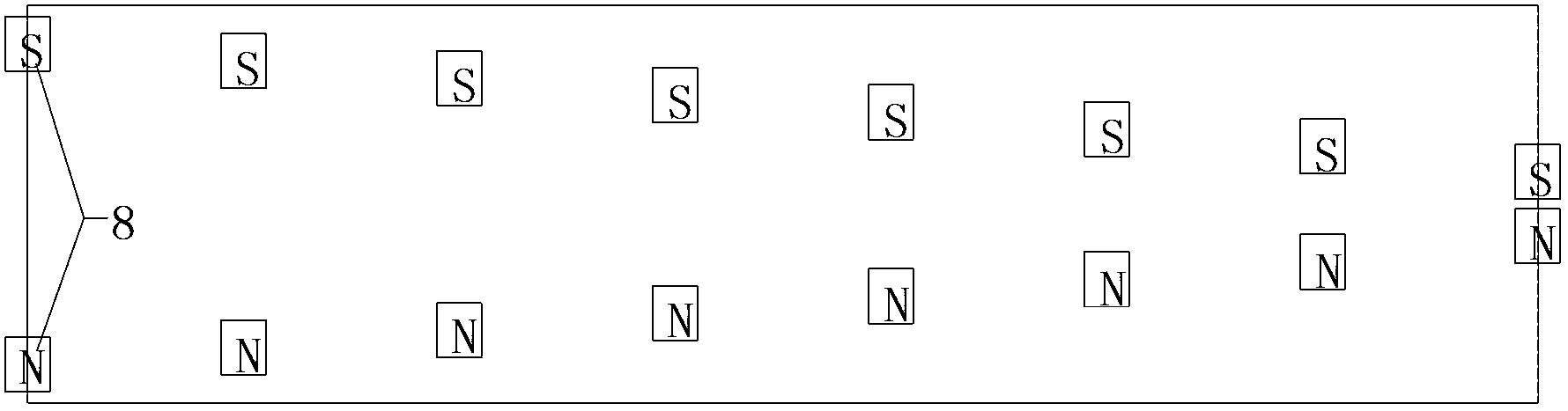
[0016] Install permanent magnets on the stator and rotor respectively with opposite magnetic poles, 16 pieces of "U"-shaped magnetic isolation plate blades (2) are embedded on the rotor, and the rotor permanent magnets (5) are embedded in the "U"-shaped magnetic isolation plate blades (2) A set of air distribution mechanism (4) is installed on the inner edge of the stator to provide pulse air supply, the angle between the outlet direction of the air injection port (11) and the radial direction is the same as the angle between the outer edge of the magnetic isolation plate blade (2) and the radial direction the same angle;

[0017] When any rotor permanent magnet (5) on the rotor (7) is located at the right end position of the corresponding stator permanent magnet (1), the rotor permanent magnet (5) will be subjected to counterclockwise suction; When the magnet (5) is located in the middle of the stator permanent ...


PUM


Abstract

The invention belongs to the field of pneumatic system energy saving, and realizes a turbine type gas magnetic engine. Permanent magnets are respectively and additionally added on a stator and a rotor of a traditional pneumatic motor, the principle that different poles of the permanent magnets are mutually attracted, identical poles of the permanent magnets are mutually repelled is utilized, and a special mechanical structure and magnet layout is designed, so the single side of each blade receives the suction force of the stator permanent magnet, the anticlockwise rotating motive power is generated. In the blade dead point position, a gas distribution mechanism can be utilized for generating strong blowing force, so blades can fast rotate to pass the dead point. Compared with the traditional pneumatic motor, the consumption of compressed air is reduced, and the rotating motive power can be continuously obtained.

Description

[0001] The invention belongs to the field of energy saving of pneumatic systems, and relates to a turbine type aeromagnetic motor. Background technique [0002] Pneumatic motors are widely used in various industries due to their simple structure, good stability and wide power range. Turbine engine is famous for its simple structure, high speed, small pulsation and stable performance. [0003] However, the pneumatic engine also has obvious disadvantages, such as low output power, low efficiency, and large gas consumption. Turbine engines require continuous air supply, and their air consumption is larger than that of ordinary pneumatic engines. If the efficiency of the pneumatic engine can be improved, the air consumption can be reduced, and the output torque can be increased, it will make a great contribution to the energy saving of the pneumatic industry. [0004] The present invention uses the suction and thrust of the permanent magnet to assist compressed air to do work, s...

Claims


Application Information

Patent Timeline
IPC IPC(8): F01D1/02F01D5/02F01D9/00F01D5/14F01D17/12H01F7/02
Inventor 盖玉收蔡茂林
Owner BEIHANG UNIV
Why Eureka
Try Eureka