

Convertible floor mat apparatus and method
a technology of floor mats and chairs, applied in the direction of carpet fasteners, paper/cardboard containers, transportation and packaging, etc., can solve the problems of chair mats with a generally smooth underside and not always suitable for use with relatively smooth flooring materials, and may slip out of place on textured flooring materials
- Summary
- Abstract
- Description
- Claims
- Application Information
AI Technical Summary
Benefits of technology
Problems solved by technology
Method used
Image

Examples
first embodiment
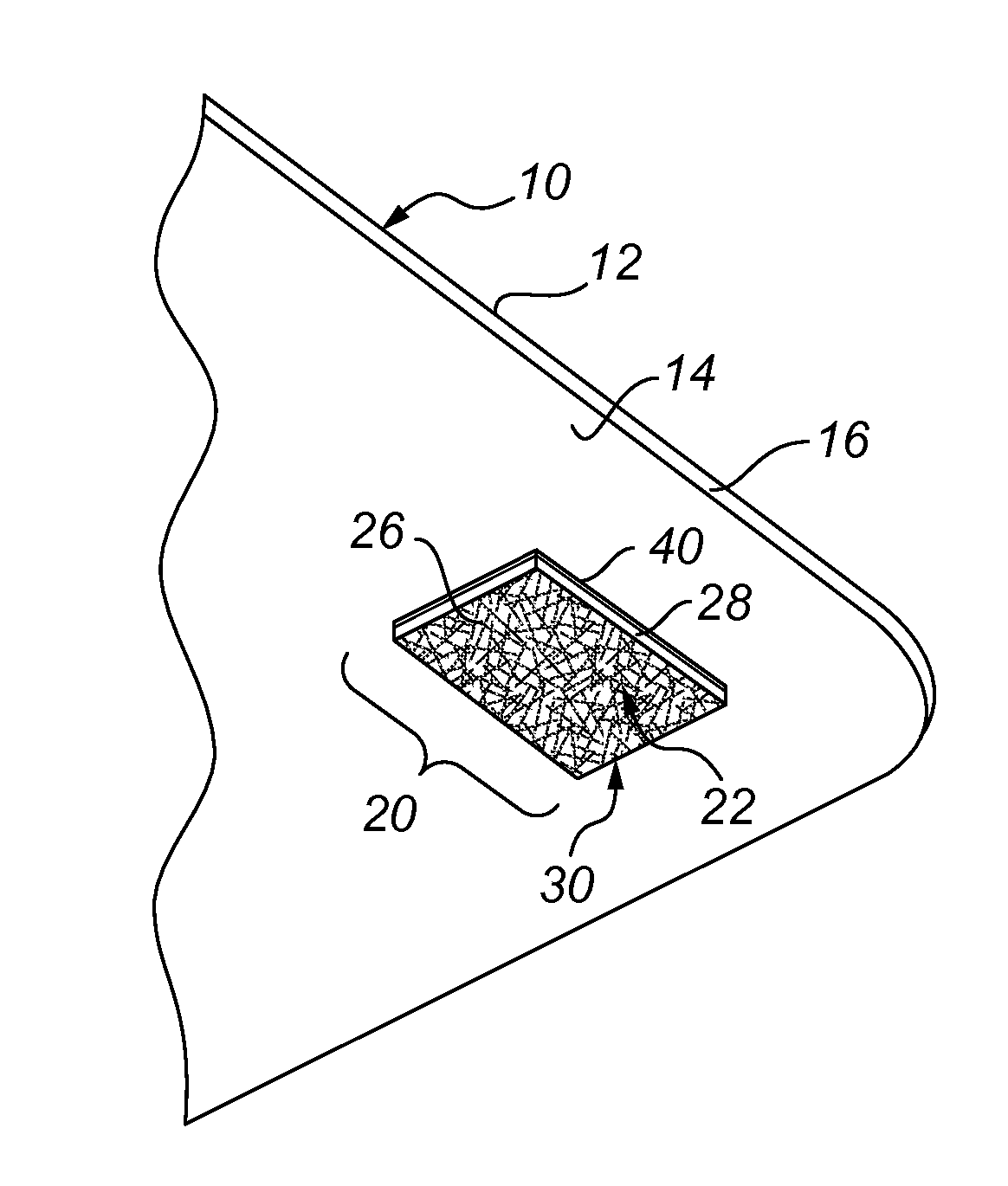
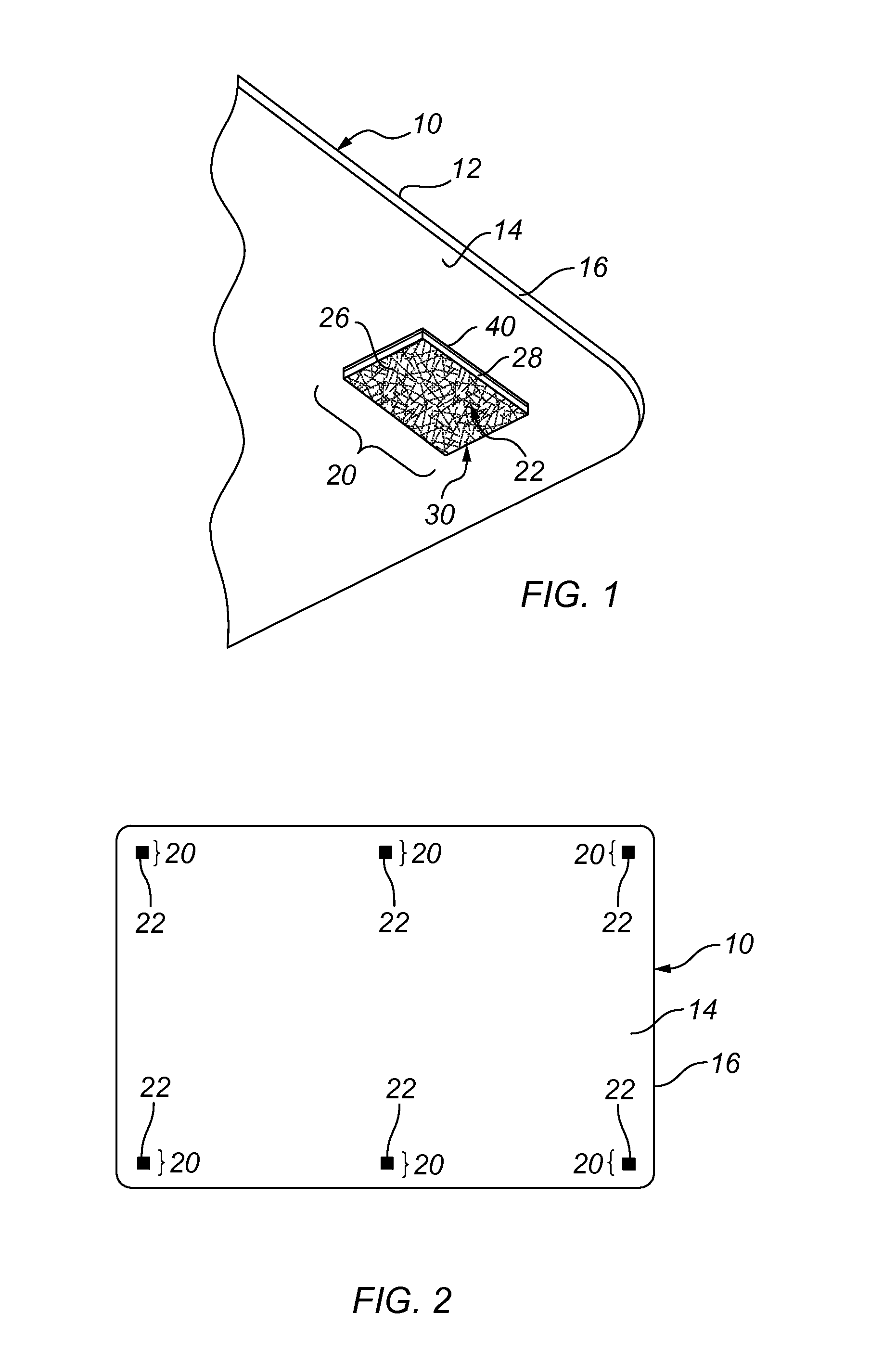
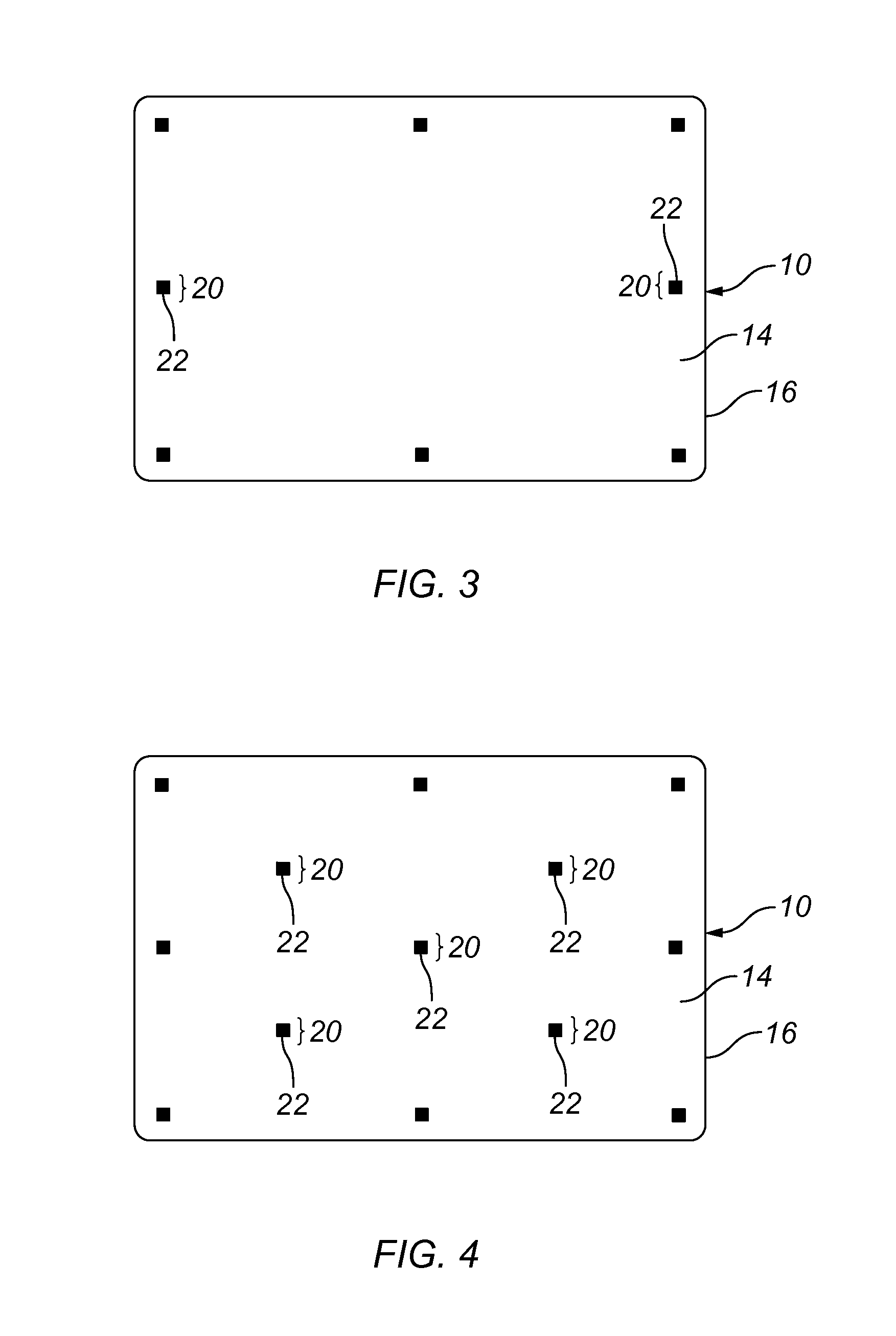
[0031]The present general inventive concept is convertible between at least two configurations, which is based on intended application of the present general inventive concept by a user. In a first embodiment, as illustrated in FIGS. 1-6, the present general inventive concept includes a body 10 having upper and lower planar surfaces 12, 14, that are parallel or substantially parallel to each other and are spaced from each other by an outermost perimeter edge 16 that extends entirely about the body 10. The planar surfaces can be smooth, relatively smooth or include various textures well known to those of ordinary skill in the art such as multiple planar surfaces, grooves, ribbing or dimples.
[0032]The body 10 is of a generally uniform thickness and may be made of a material such as, but not limited to rubber, plastic, and / or the like, that is sufficiently durable to withstand wear and / or tear depending on and during use of the present general inventive concept, e.g., to support a chai...
second embodiment
[0039]In a second embodiment, as illustrated in FIGS. 7-12, the present general inventive concept includes a body 110 having upper and lower generally smooth, planar surfaces 112, 114, that are facing each other and are spaced from each other by an outermost perimeter edge 116 that extends entirely about the body 110. The planar surfaces 112 and 114 can also be parallel to each other or substantially parallel to each other.
[0040]The body 110 is of a generally uniform thickness and may be made of a material such as, but not limited to rubber, plastic, and / or the like, that is sufficiently durable to withstand wear and / or tear depending on and during use of the present general inventive concept, e.g., to support a chair on the upper surface 112 of the body 110. The body 110 may be made of a material that is transparent, translucent, opaque, and / or a combination thereof. The body 110 may have a pattern, for instance, on the upper surface 112 or the lower surface 114 of the body, to for...
third embodiment
[0048]In the third embodiment, the body 210 is of a generally uniform thickness and may be made of a material such as, but not limited to rubber, plastic, and / or the like, that is sufficiently durable to withstand wear and / or tear depending on and during use of the present general inventive concept, e.g., to support a chair on the upper surface 212 of the body 210. The body 210 may be made of a material that is transparent, translucent, opaque, and / or a combination thereof. The body 210 may have a pattern, for instance, on the lower r surface 214 of the body, to form a design thereon.
[0049]In the third embodiment, shown in FIG. 13 one or a plurality of friction-increasing elements 222 can be permanently or removably affixed to the lower surface 214 of the body 210 via an adhesive coating such as glue or the like. For instance, the lower surface 212 may be provided with peel-off elements that, when peeled off, expose a sticky or adhesive surface. Further, the adhesive coating can be ...
PUM
| Property | Measurement | Unit |
|---|---|---|
| friction | aaaaa | aaaaa |
| perimeter | aaaaa | aaaaa |
| length | aaaaa | aaaaa |
Abstract
Description
Claims
Application Information