Vehicle operating condition determining system, driving assist system, and operating condition determining method

Active Publication Date: 2013-08-01
TOYOTA JIDOSHA KK
View PDF9 Cites 15 Cited by
  • Summary
  • Abstract
  • Description
  • Claims
  • Application Information

AI Technical Summary

Benefits of technology

[0029]Also, the vehicle driving assist system according to the above aspect of the invention is able to res

Problems solved by technology

Also, when the running speed of the vehicle is high, the steering angle may be small even when a lane change is made by the inte

Method used


Image

  • Vehicle operating condition determining system, driving assist system, and operating condition determining method
  • Vehicle operating condition determining system, driving assist system, and operating condition determining method
  • Vehicle operating condition determining system, driving assist system, and operating condition determining method

Examples


Example

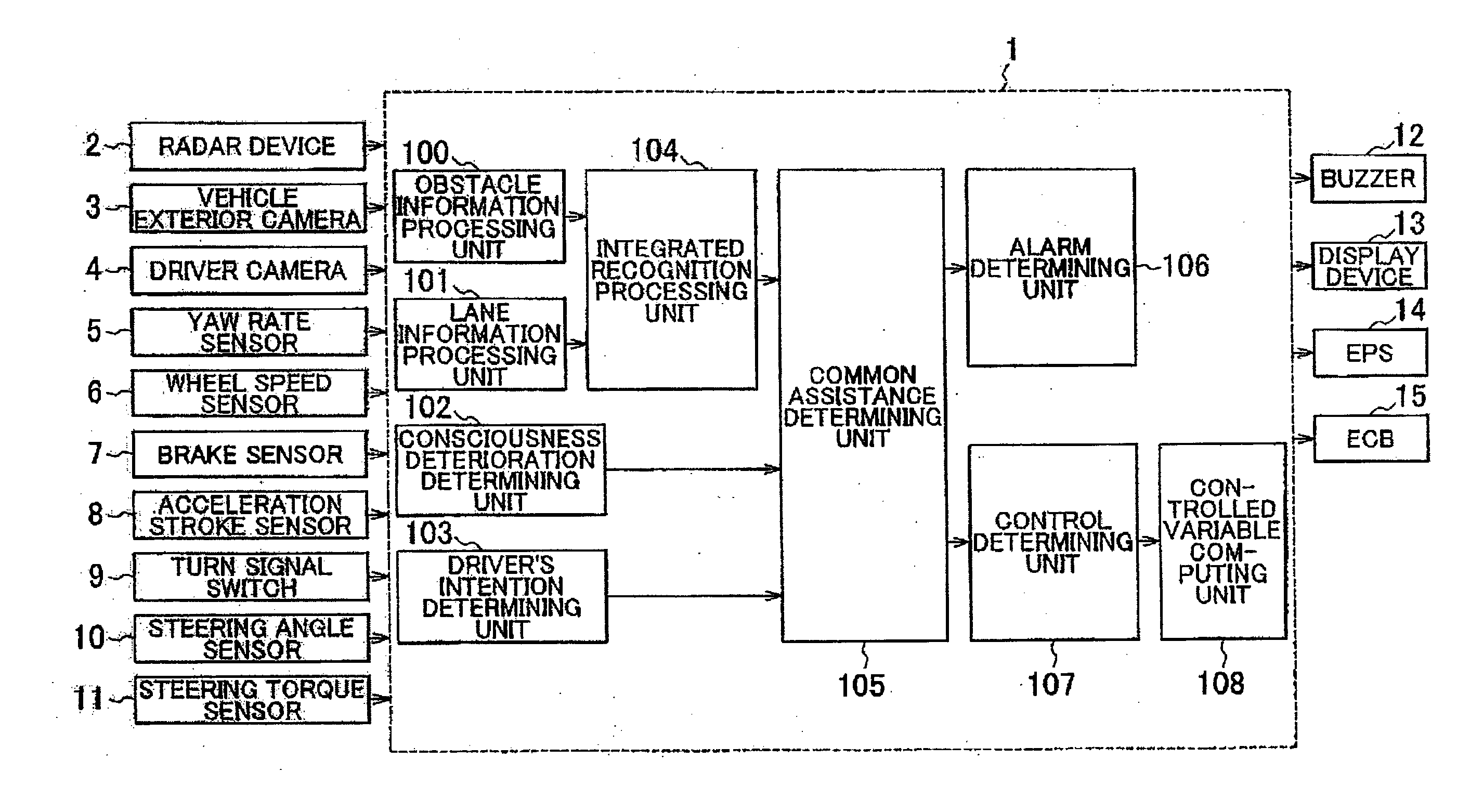
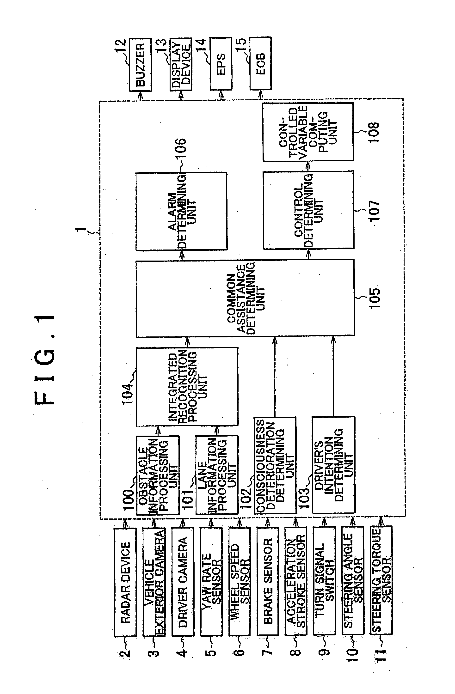
[0036]Initially, a first embodiment of the invention will be described with reference to FIG. 1 through FIG. 3. FIG. 1 is a block diagram illustrating the configuration (functional units) of a vehicle driving assist system to which the invention is applied. As shown in FIG. 1, a control unit (ECU) 1 for driving assist is installed on the vehicle.

[0037]The ECU 1 is an electronic control unit including CPU, ROM, RAM, backup RAM, and an I / O interface. Various sensors, such as a radar device 2, vehicle exterior camera 3 for photographing the exterior or outside of the vehicle, driver camera 4 for photographing the driver, yaw rate sensor 5, wheel speed sensor 6, brake sensor 7, acceleration stroke sensor 8, turn signal switch 9, steering angle sensor 10, and a steering torque sensor 11, are electrically connected to the ECU 1, and the ECU 1 receives output signals of these sensors.

[0038]The radar device 2 is mounted on the front side of the vehicle, for example, and is operable to trans...

Example

[0082]Next, a second embodiment of the invention will be described with reference to FIG. 4. In the following, only the arrangements of the second embodiment which are different from those of the above-described first embodiment will be described, and the same or similar arrangements will not be described.

[0083]In the first embodiment as described above, it is determined whether the driver intentionally operates the steering wheel, depending on the presence or absence of the steering holding period, and then execution of the driving assisting process is restricted based on the result of the determination. However, in the second embodiment, execution of the driving assisting process is restricted depending on the presence or absence of the steering holding period.

[0084]FIG. 4 is a flowchart illustrating a routine executed by the ECU 1 when it determines whether execution of the driving assisting process is to be restricted. This routine is stored in advance in the ROM of the ECU 1, a...


PUM


Abstract

A vehicle operating condition determining system determines, when a turning angle of wheels or a steering angle of a steering wheel changes, that the turning angle of the wheels or the steering angle of the steering wheel changes due to a driver's intention, under a condition that the magnitude of steering torque applied to a steering device is kept equal to or larger than a threshold value after the torque reaches a peak, for a period of time equal to or longer than a reference time.

Description

BACKGROUND OF THE INVENTION[0001]1. Field of the Invention[0002]The invention relates to an operating condition determining system, an operating condition determining method, and a driving assist system, for determining operating conditions concerning operations performed by a driver of a vehicle.[0003]2. Description of Related Art[0004]A technology of assisting the driver in a driving operation in order to enhance the safety of the vehicle, such as an automobile, has been proposed. For example, a system that informs the driver of the presence of an obstacle or deviation of the vehicle from a running course, and a system that assists the driver in an operation to circumvent or avoid the obstacle or an operation to cause the vehicle to return to the course are known.[0005]It is desirable that the systems as described above do not operate in response to vehicle behaviors caused by the driver's intentional operations. In Japanese Patent Application Publication No. 2006-515545 (JP-A-200...

Claims


Application Information

Patent Timeline
IPC IPC(8): B62D15/02
CPCB60W30/12B60W40/09B60W50/10B62D15/021B60W2540/18B62D1/286B62D15/025B60W2510/202B60T2201/10B60W2520/125B62D5/003B60W2520/14
Inventor YOSHIHAMA, YUKI
Owner TOYOTA JIDOSHA KK
Why Eureka
Try Eureka