Code generation for control design

a control design and code generation technology, applied in the creation/generation of source code, program control, instruments, etc., can solve the problem of labor-intensive rewriting of code to separate functions of legacy blocks (e.g., those that were not coded with complete separation of these functions)

Active Publication Date: 2013-08-01
THE MATHWORKS INC
View PDF10 Cites 35 Cited by
  • Summary
  • Abstract
  • Description
  • Claims
  • Application Information

AI Technical Summary

Problems solved by technology

Rewriting code to separate functions for legacy blocks (e.g., that were ...

Method used


Image

  • Code generation for control design
  • Code generation for control design
  • Code generation for control design

Examples


Embodiment Construction

[0012]The following detailed description refers to the accompanying drawings. The same reference numbers in different drawings identify the same or similar elements. Also, the following detailed description does not limit the invention.

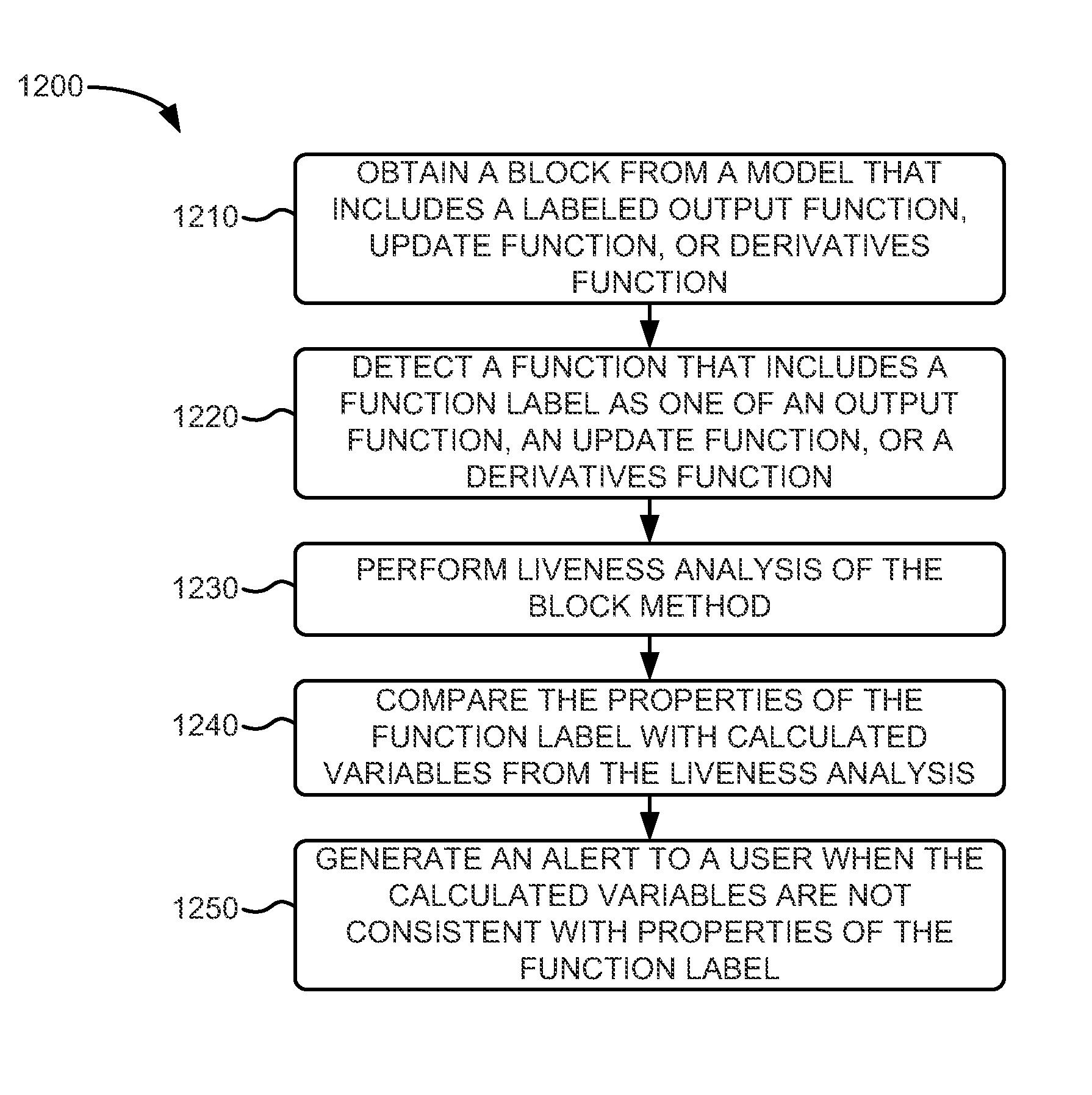
[0013]An implementation described herein relates to automated code generation associated with a graphical model in a modeling application. Particularly, the automatically generated code may convert code modules (referred to herein as blocks) with step functions into code with separate update and / or output functions that can then be used for control analysis and design.

[0014]A dynamic system may be characterized by one or more differential and / or difference equations. The one or more differential and / or difference equations may be represented by a graphical model in a modeling system. In order to simulate the dynamic system represented by the graphical model, the one or more differential and / or difference equations may need to be solved for par...


PUM


Abstract

A method, performed by a computer device, includes obtaining an in-memory representation of computer code from a block step method of an executable model in a modeling application, wherein the computer code in-memory representation includes one or more variables. The method also includes identifying, from the one or more variables, a subset of persistent variables and determining if any of the one or more variables in the subset of persistent variables are state variables. When none of the subset of persistent variables are state variables, a block output method is generated based on the computer code in-memory representation and the one or more variables. When the subset of persistent variables includes a state variable, both the block output method and a block update method are generated based on the computer code in-memory representation and the one or more variables.

Description

[0001]This patent application is a continuation-in-part of U.S. patent application Ser. No. 13 / 291,899, entitled “VISUALIZATION OF DATA DEPENDENCY IN GRAPHICAL MODELS” and filed on Nov. 8, 2011, which is hereby incorporated by reference in its entirety. This patent application is also a continuation-in-part of U.S. patent application Ser. No. 13 / 291,907, entitled “GRAPH THEORETIC LINEARIZATION AND SENSITIVITY ANALYSIS” and filed on Nov. 8, 2011, which is hereby incorporated by reference in its entirety.BACKGROUND INFORMATION[0002]A large variety of systems, such as mechanical systems, electrical systems, biological systems, and / or computer systems, may be represented as dynamic systems. Computational tools have been developed to model, simulate, and / or analyze dynamic systems. A computational tool may represent a dynamic system as a graphical model. The graphical model may include blocks that may represent components of the dynamic model. The blocks may be connected to represent rel...

Claims


Application Information

Patent Timeline
IPC IPC(8): G06F9/44
CPCG06F8/10G06F17/5009G06F8/35G06F17/13G06F8/30G06F30/20
Inventor ZHANG, FUHAN, ZHIYEDDANAPUDI, MURALI K.MOSTERMAN, PIETER J.
Owner THE MATHWORKS INC
Why Eureka
Try Eureka