
Multi-screen display apparatus and luminance control method

a multi-screen display and luminance control technology, applied in the direction of electric variable regulation, process and machine control, instruments, etc., can solve the problem of impaired luminance homogeneity between the respective screens of the multi-screen display

Inactive Publication Date: 2013-08-08
TRIVALE TECH
View PDF2 Cites 23 Cited by
  • Summary
  • Abstract
  • Description
  • Claims
  • Application Information

AI Technical Summary

Benefits of technology

The present invention is about a display screen that can show the same brightness on each screen. This invention helps make the display look better and more consistent across all screens.

Problems solved by technology

In the multi-screen display apparatus, however, the following problems have been raised.
For example, in the case where one of LED's inside the R-LED array has a failure with the result that the corresponding LED becomes incapable of being lit up, the driving circuit with the failed LED stops the driving operation of the LED.
In particular, in the case of the multi-screen display apparatus constituted by a plurality of image display apparatuses, due to a change of luminance or the like of a certain image display apparatus, homogeneity in luminance among the respective screens on the multi-screen is impaired.

Method used


Image

  • Multi-screen display apparatus and luminance control method
  • Multi-screen display apparatus and luminance control method
  • Multi-screen display apparatus and luminance control method

Examples


Embodiment Construction

[0025]Referring to drawings, the following description will explain a preferred embodiment of the present invention. In the following explanation, the same components are indicated by the same reference numerals. The names and functions thereof are the same. Therefore, the detailed explanation thereof will be sometimes omitted.

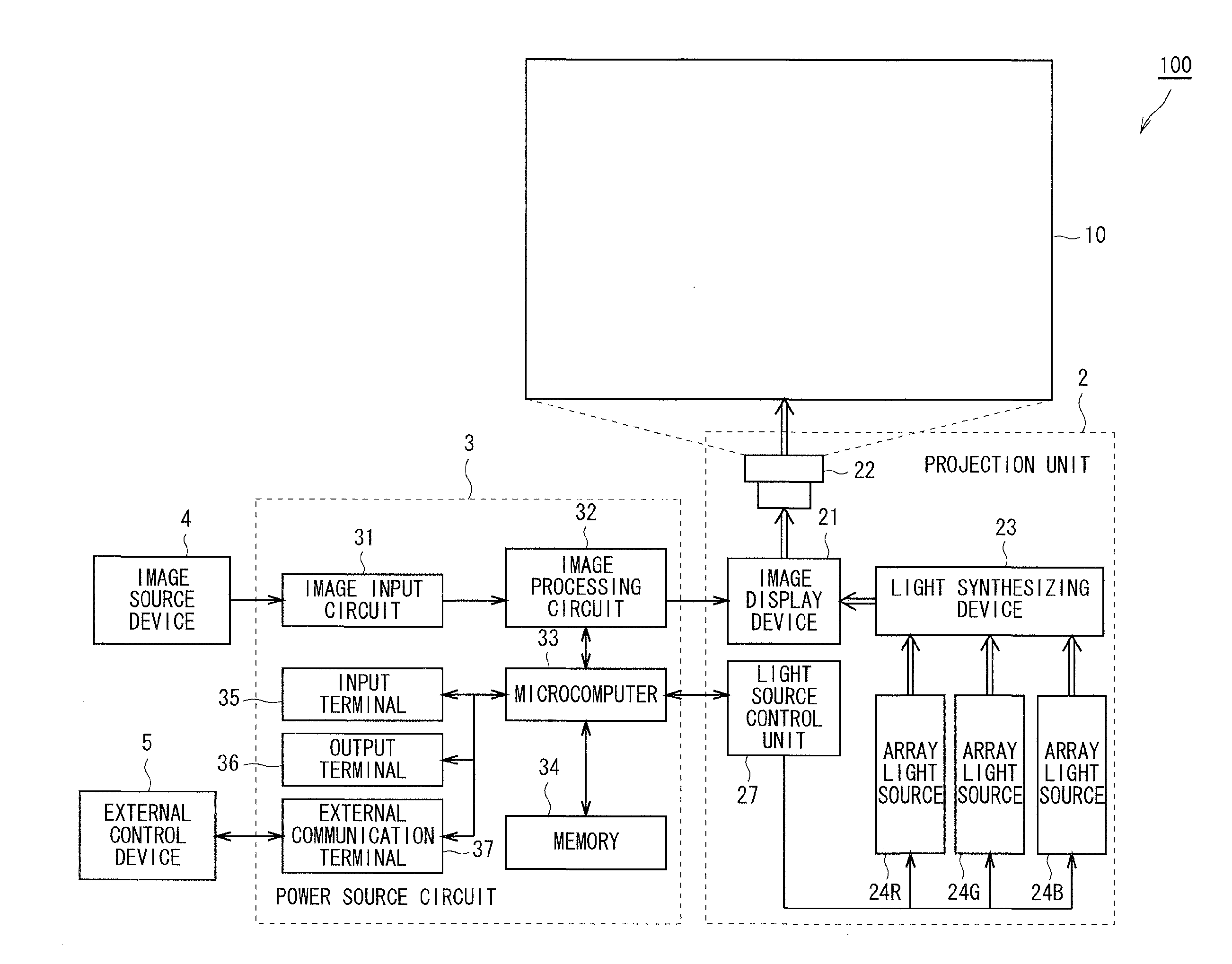
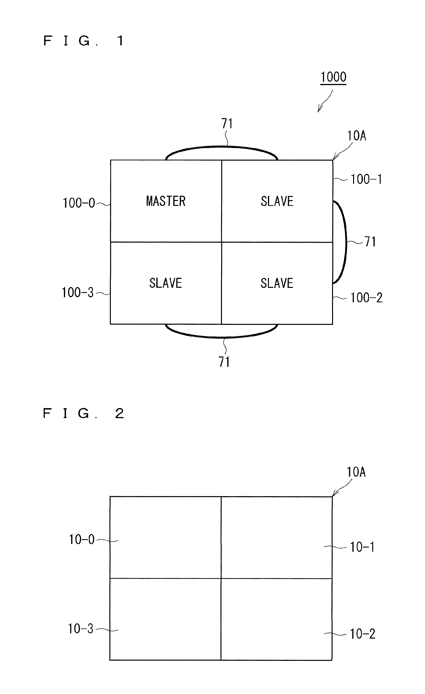
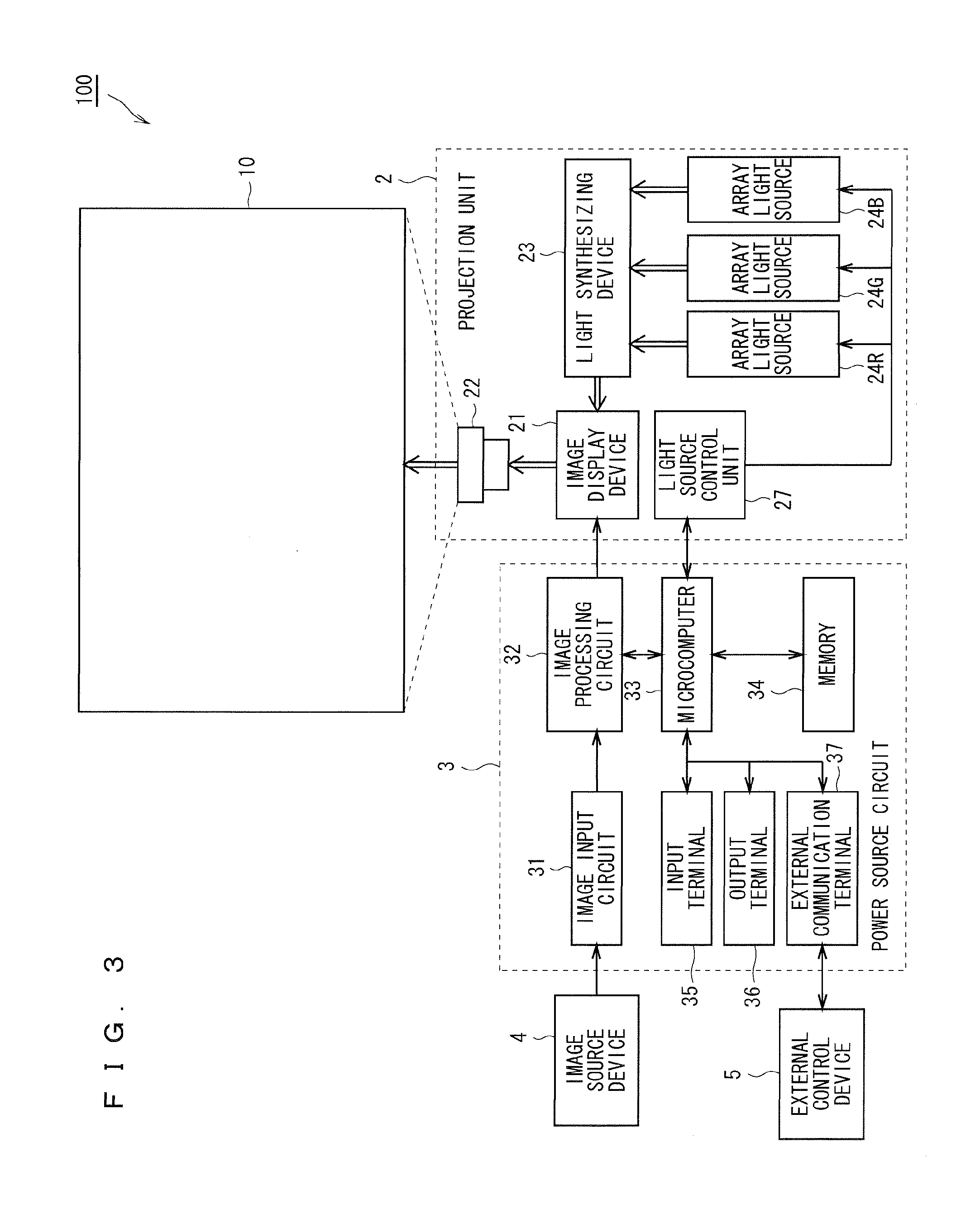
[0026]FIG. 1 is a view showing a structure of a multi-screen display apparatus 1000 in accordance with the preferred embodiment of the present invention. The multi-screen display apparatus 1000 is an image display apparatus (multi-vision) of a projection type that projects an image on the screen.

[0027]As shown in FIG. 1, the multi-screen display apparatus 1000 includes image display apparatuses 100-0, 100-1, 100-2 and 100-3. The respective image display apparatuses 100-0, 100-1, 100-2 and 100-3 the detailed descriptions of which will be given later have the same structure. In the following description, each of the image display apparatuses 100-0, 100-1, 100-2 ...


PUM


Abstract

In the case where luminance of light to be irradiated onto a multi-screen is not homogenized over the entire multi-screen, each of an image display apparatus and image display apparatuses carries out a homogenizing process of light to be irradiated onto a multi-screen over the entire multi-screen.

Description

BACKGROUND OF THE INVENTION[0001]1. Field of the Invention[0002]The present invention relates to a multi-screen display apparatus that displays an image on a multi-screen constituted by a plurality of screens and a luminance control method.[0003]2. Description of the Background Art[0004]In recent years, in a projection-type image display apparatus, light sources utilizing light emitting diodes (LED (Light Emitting Diodes)) have been used in place of conventional lamp light sources. In particular, in a display apparatus of DLP (registered trade mark) (Digital Light Processing) system that uses DMD's (Digital Micromirror Devices), LED's that emit red light, LED's that emit green light and LED's that emit blue light are used. In the display apparatus of the DLP (registered trade mark) system, these LED's of three colors are lit up on in a time sharing manner.[0005]As the projection-type image display apparatus utilizing LED's as light sources, those using LED arrays constituted by a pl...

Claims


Application Information

Patent Timeline
Patent Type & Authority Applications(United States)
IPC IPC(8): H05B37/03H05B44/00
CPCH05B37/03H05B33/0893H05B33/0827H04N9/3147H04N9/3155H04N9/3164H04N9/3182H04N9/3191H05B45/58H05B45/46H05B47/20
Inventor YONEOKA, ISAOASAMURA, YOSHINORIMATOBA, TAKASHI
Owner TRIVALE TECH
Learn More