Catalyst holder and agitation system for converting stirred tank reactor to fixed bed reactor

a technology of agitation system and catalyst, which is applied in the preparation of amino compounds, physical/chemical process catalysts, pressurized chemical processes, etc., can solve the problems of shortening the catalyst life, affecting the safety of chemical process, and inherently problematic slurry phase reaction systems,

Inactive Publication Date: 2006-07-11
AIR PROD & CHEM INC
View PDF6 Cites 4 Cited by
  • Summary
  • Abstract
  • Description
  • Claims
  • Application Information

AI Technical Summary

Benefits of technology

[0017]an ability to eliminate reactor loops, pumps, etc. commonly used in fixed bed and monolith catalytic reactors, particularly those that employ external heat exchangers;
[0018]an ability to enhance the solubilization of the reactant gas in the reactant liquid for catalytic reaction;
[0019]an ability to maintain homogeneity of the reactants and reaction products;
[0020]an ability to enhance circulation rate and effect short mixing and blend times due to the high flow rate generated by the turbine impeller through a fixed bed catalytic reactor;
[0022]an ability to overcome agitation problems where the fixed bed catalytic reactor is affixed to the agitation mechanism and rotated.

Problems solved by technology

These slurry phase reaction systems are inherently problematic in chemical process safety, operability and productivity.
The finely divided, powdered catalysts are often pyrophoric and require extensive operator handling during reactor charging and filtration.
By the nature of their heat cycles for start-up and shutdown, slurry systems promote co-product formation which can shorten catalyst life and lower yield to the desired product.
While this reactor technology does eliminate much of the handling and waste problems associated with stirred tank reactors, there are a number of engineering challenges.
E.g., inadequate mixing and inadequate heat transfer have not permitted the general application of fixed bed reactor technology to reactions involving many organic compounds.

Method used


Image

  • Catalyst holder and agitation system for converting stirred tank reactor to fixed bed reactor
  • Catalyst holder and agitation system for converting stirred tank reactor to fixed bed reactor
  • Catalyst holder and agitation system for converting stirred tank reactor to fixed bed reactor

Examples


example 1

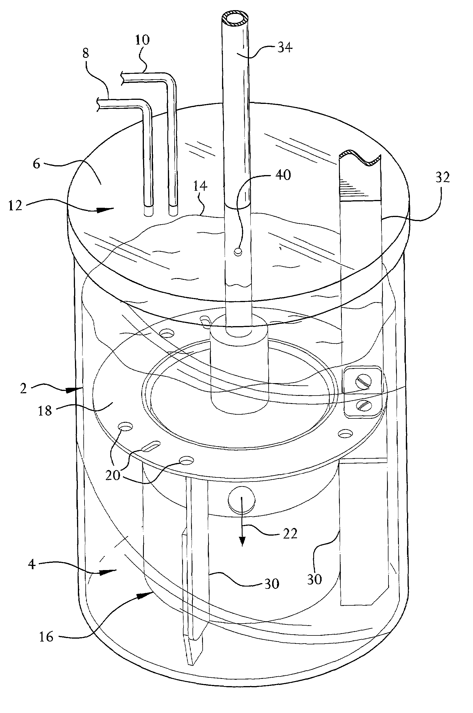
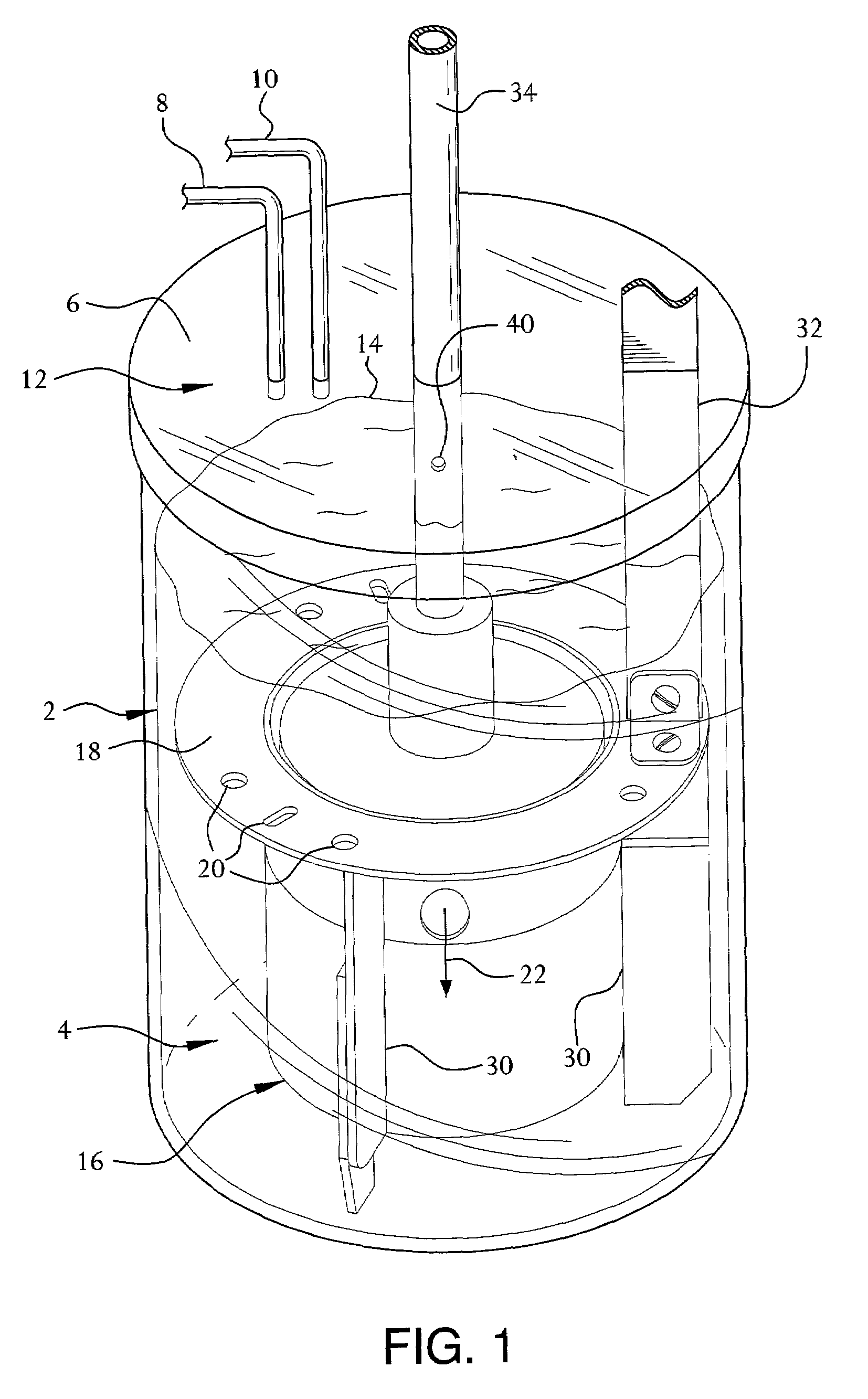
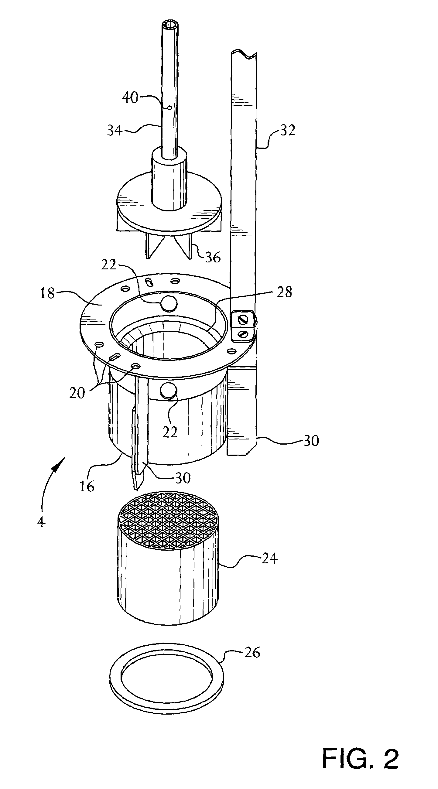
Hydrogenation of Nitrobenzene in a Stirred Tank Autoclave Converted to Fixed Bed Reactor

[0052]In effecting a two-phase reaction such as the hydrogenation of nitrobenzene in a 2 liter Parr reactor fitted with the catalyst holder and agitation system.

Catalyst Pretreatment

[0053]A 2-inch long×2-inch diameter 5% Pd / carbon monolith catalyst having 400 channels per square inch was mounted in the fixed bed catalyst holder described in FIG. 1 providing an effective monolith catalyst diameter of 1.75 inches. This assembly was placed in the 2 L Parr reactor and sealed. After room temperature dry leak testing with nitrogen, then hydrogen, then depressurizing, one liter of 2-propanol was added to the reactor. The reactor was pressurized to 200 psig with hydrogen, heated over 30 minutes to 140° C. with stirring at 1000 rpm, maintained at 140° C. for 30 minutes, and then cooled to room temperature. The reactor was emptied.

Nitrobenzene Hydrogenation

[0054]To the above Parr reactor including the mono...


PUM

PropertyMeasurementUnit
velocityaaaaaaaaaa
diameteraaaaaaaaaa
temperatureaaaaaaaaaa

Abstract

This invention relates to apparatus particularly a monolith catalytic reactor in a stirred tank reactor. The stirred tank reactor including the fixed bed catalytic reactor apparatus comprises:an housing having an open top and open bottom portion supportably maintained with said tank, said housing having a substantially outwardly extending, horizontal baffle near its top portion said baffle having a least one perforation in its surface, and said housing having at least one perforation in the wall near its top portion;a fixed bed catalyst system supportably retained within said housing permitting both liquid and gas flow therethrough; and,an agitator shaft terminating in a turbine blade substantially adjacent the perforation in the wall of said housing, said agitator having a passageway including an opening in an upper portion thereof to the interior of an upper part of said tank and terminating in an opening adjacent the turbine blade.

Description

BACKGROUND OF THE INVENTION[0001]Industrial two phase reactions, such as hydrogenation reactions, are often performed by using finely divided powdered slurry catalysts in stirred-tank reactors. These slurry phase reaction systems are inherently problematic in chemical process safety, operability and productivity. The finely divided, powdered catalysts are often pyrophoric and require extensive operator handling during reactor charging and filtration. By the nature of their heat cycles for start-up and shutdown, slurry systems promote co-product formation which can shorten catalyst life and lower yield to the desired product.[0002]An option to the use of finely divided powder catalysts in stirred reactors is the use of fixed bed reactors, e.g., pelleted and particulate catalysts or monolith catalysts. While this reactor technology does eliminate much of the handling and waste problems associated with stirred tank reactors, there are a number of engineering challenges. E.g., inadequat...

Claims


Application Information

Patent Timeline
Patent Type & Authority Patents(United States)
IPC IPC(8): C07C209/00B01J3/00B01F7/16B01J3/04B01J8/02B01J10/00B01J19/00B01J19/18B01J19/24C07B61/00C07C209/36C07C211/46C07C211/47
CPCB01J3/04B01J8/0292C07C209/36B01J10/007B01J19/006B01J19/1875B01J19/2485C07C211/46C07C211/47B01J2219/30475B01J2219/30215B01J2208/00176B01J2208/00203B01J2219/00083B01J2219/00094B01J2219/00768B01J2219/00777B01J2219/30203
Inventor MACHADO, REINALDO MARIOKONISKI, JAMES EDWARDKOHLER, STEPHEN
Owner AIR PROD & CHEM INC
Why Eureka
Try Eureka