
Carbon nanotube explosives

a carbon nanotube and explosive material technology, applied in the field of explosive materials, can solve the problem of rapid chemical reaction

Active Publication Date: 2013-08-15
ARMY US SEC THE
View PDF1 Cites 3 Cited by
  • Summary
  • Abstract
  • Description
  • Claims
  • Application Information

AI Technical Summary

Benefits of technology

The patent describes attaching a solid oxidizer to a carbon nanotube for various uses including creating a micothruster (a device used to propel smaller objects) and generating energy through chemical reactions. Additionally, it suggests that by combining these components into one object, they could also act as a primarization agent to initiate another explosion.

Problems solved by technology

The technical problem addressed by this patent is the development of a small explodable substance or device that can produce precise controlled amounts of energy without causing excessive damage or injury during its usage. This type of technology could have various applications including but not limited to military operations, spying, and manipulating objects.

Method used


Image

  • Carbon nanotube explosives
  • Carbon nanotube explosives
  • Carbon nanotube explosives

Examples


example

[0035]Multiwalled carbon nanotubes were produced using a thermal chemical vapor deposition technique which exposed a mixture of ferrocene and xylene vapor to a patterned SiO2 / Si substrate in a quartz tube furnace. The substrate within the quartz tube was held at 770° C. and the gas mixture was allowed to flow through the tube for times between 30 to 60 minutes. Before passing the ferrocene-xylene gas mixture through the quartz, argon gas at a pressure of approximately 100 mTorr was present to prevent the patterned SiO2 / Si substrate surface from oxidizing. Then, and after the furnace was heated to the deposition temperature of 770° C., a solution of ferrocene (0.5 mg) in xylene (50 mL) was pre-vaporized at 180° C. and introduced into a quartz tube and allowed to flow over the substrate. It is appreciated that the pre-vaporized ferrocene / xylene mixture served as both a carbon source and a catalyst with the xylene providing the carbon atoms and iron from the ferrocene serving as the ca...


PUM


Abstract

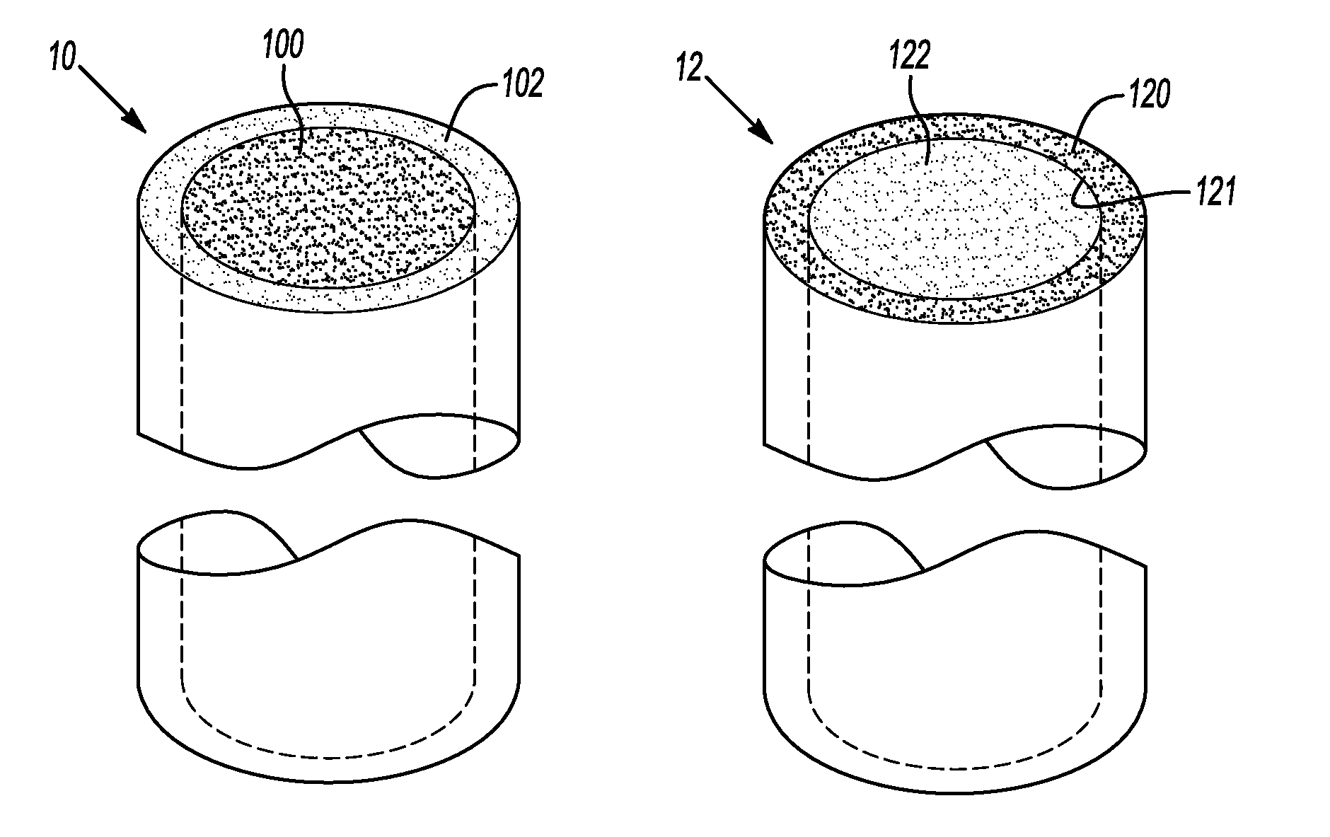
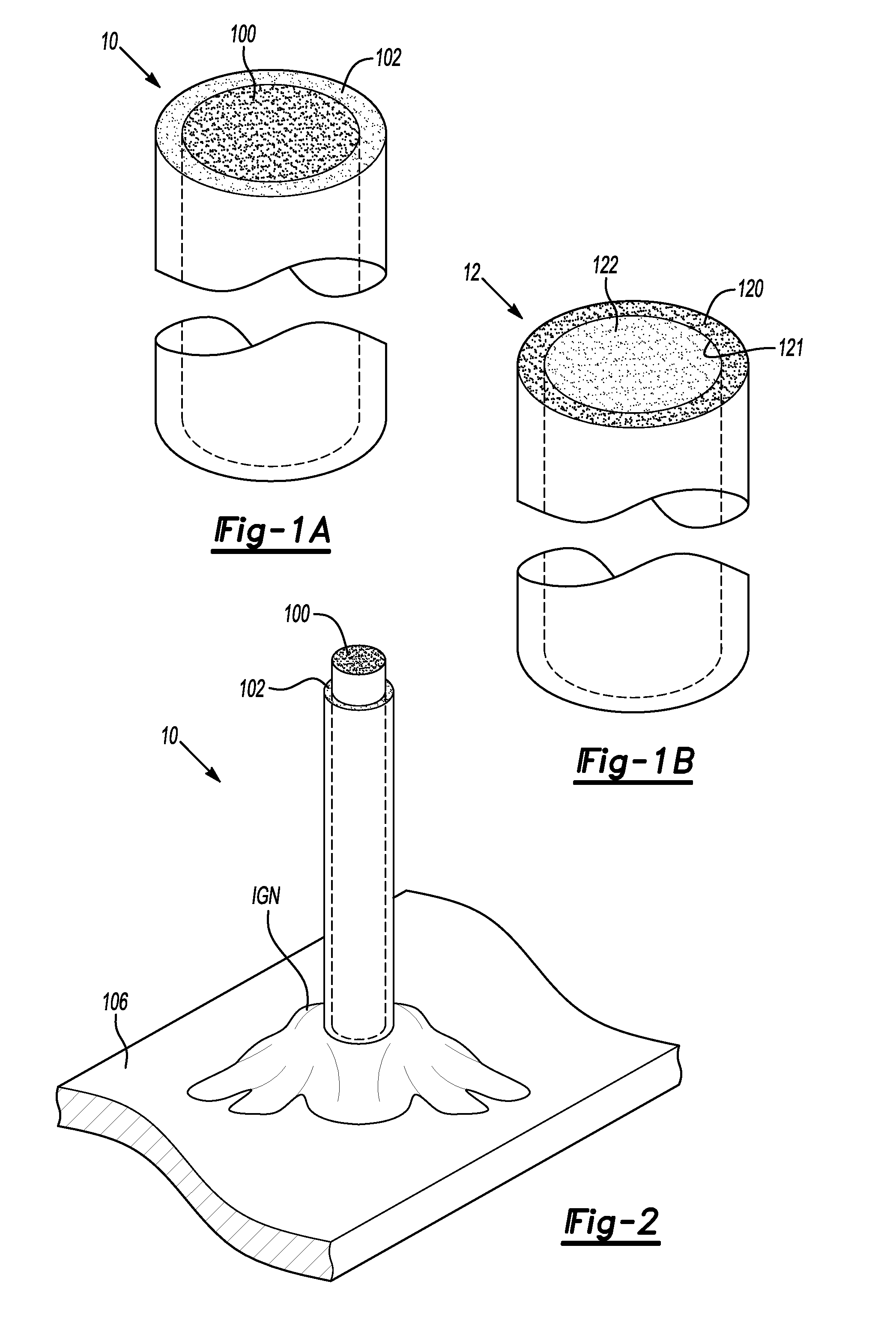
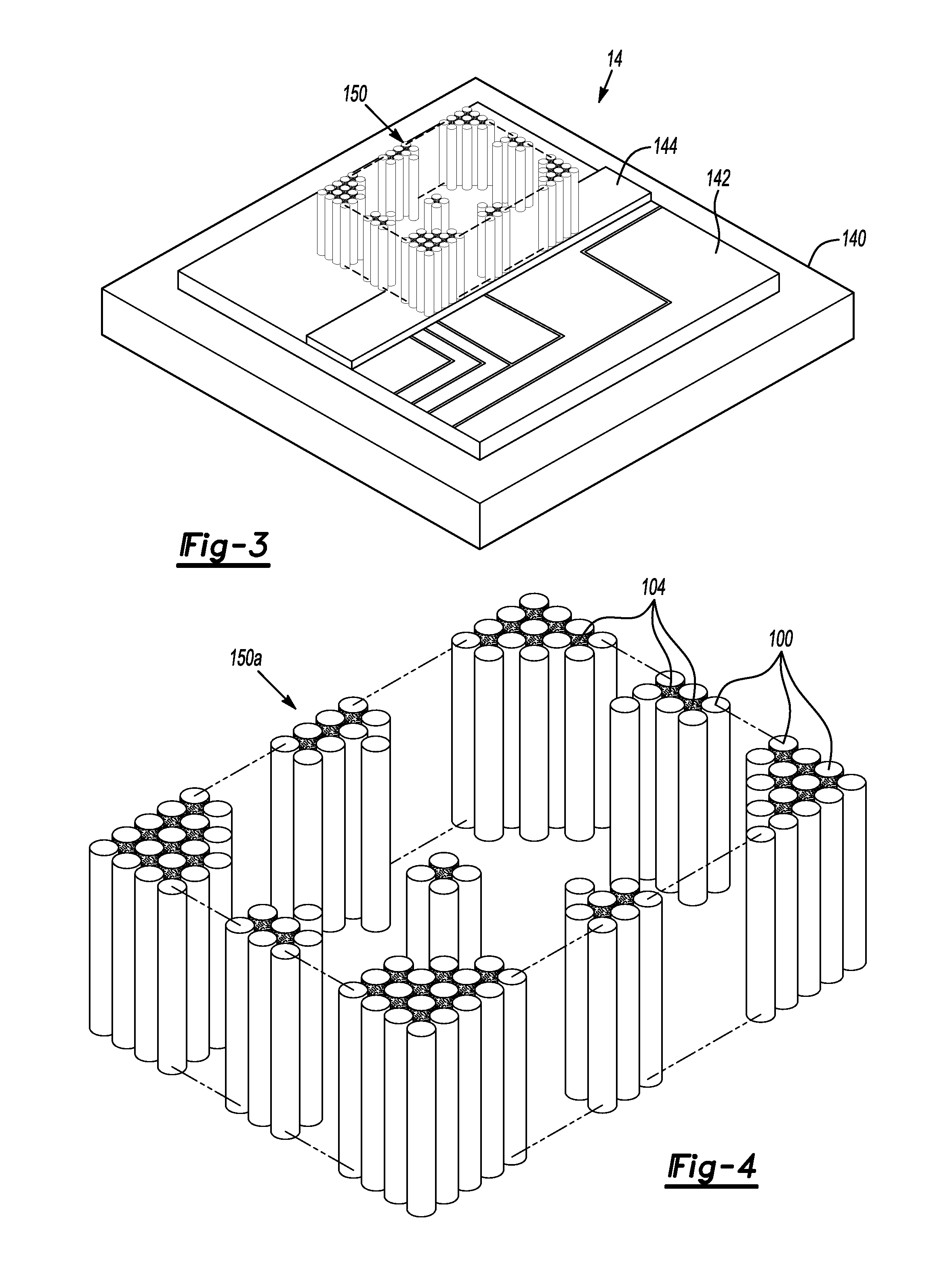
A micro-explosive material is provided. The micro-explosive material can include a carbon nanotube and a solid oxidizer attached to the carbon nanotube. The carbon nanotube with the solid oxidizer attached thereto is operable to burn per an exothermic chemical reaction between the carbon nanotube and the solid oxidizer such that a controlled burn and/or an explosive burn is provided. The micro-explosive material can be used as a heat generator, a gas generator, a micro-thruster, a primer for use with a larger explosive material, and the like.

Description


Claims


Application Information

Patent Timeline
Owner ARMY US SEC THE
Learn More