Spinning reel waterproofing member and spinning reel using the same

a technology of waterproofing member and spinning reel, which is applied in the direction of reels, engine seals, animal husbandry, etc., can solve the problems of increasing water pressure acting on the inner peripheral portion of the seal member and and achieve the effect of deteriorating waterproofing performance of the seal member

Active Publication Date: 2013-08-15
SHIMANO INC
View PDF9 Cites 33 Cited by
  • Summary
  • Abstract
  • Description
  • Claims
  • Application Information

AI Technical Summary

Benefits of technology

[0007]The seal member of the well-known spinning reel described above can prevent water ingress into the roller clutch because the seal member is placed with the inner peripheral portion of the seal member projecting in the radial direction in such a way that the inner peripheral portion is in contact with the outer peripheral surface of the boss portion of the rotor. However, if a large amount of water flows into the interstice between the rear surface of the rotor disposed on the front portion of the tubular portion and the front surface of the seal member, there arises the concern that the water pressure acting on the inner peripheral portion of the seal member will increase and that the waterproofing performance of the seal member will deteriorate.

Problems solved by technology

However, if a large amount of water flows into the interstice between the rear surface of the rotor disposed on the front portion of the tubular portion and the front surface of the seal member, there arises the concern that the water pressure acting on the inner peripheral portion of the seal member will increase and that the waterproofing performance of the seal member will deteriorate.

Method used


Image

  • Spinning reel waterproofing member and spinning reel using the same
  • Spinning reel waterproofing member and spinning reel using the same
  • Spinning reel waterproofing member and spinning reel using the same

Examples


first embodiment

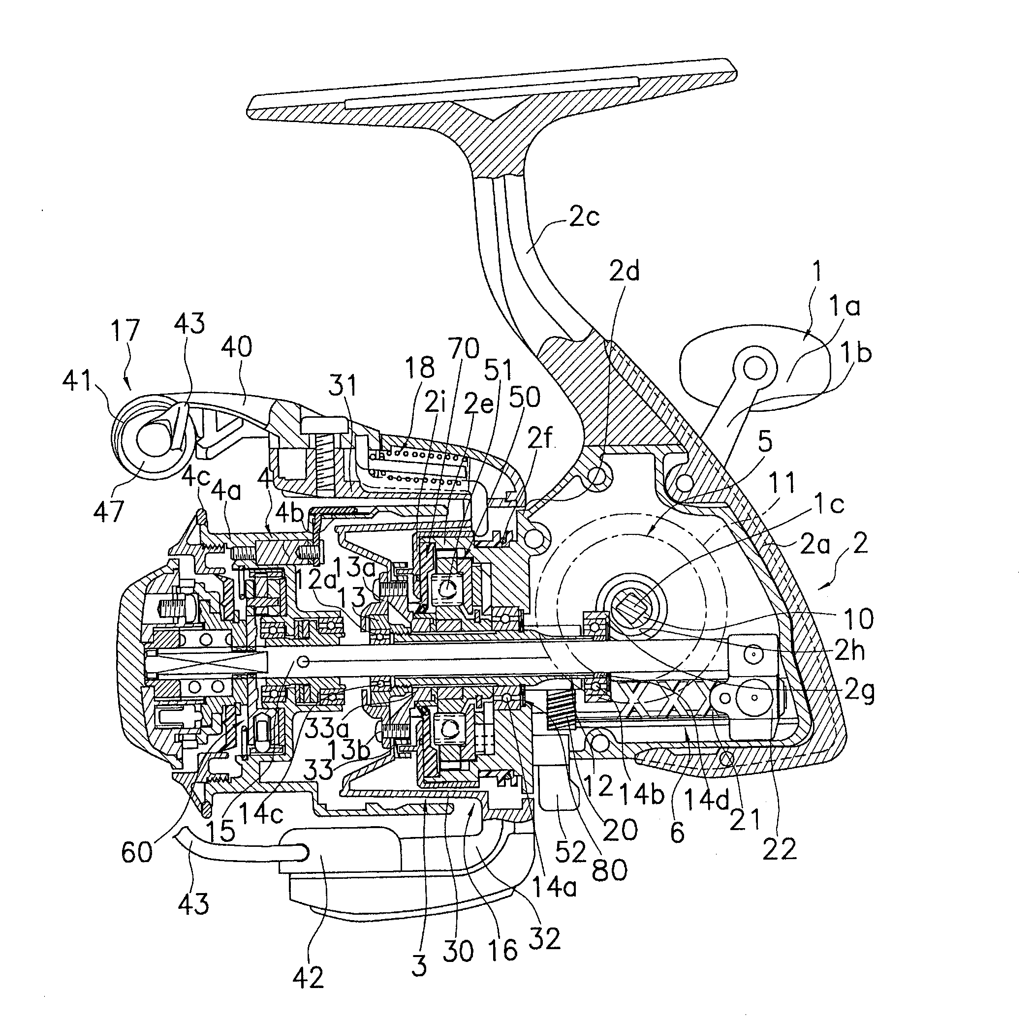
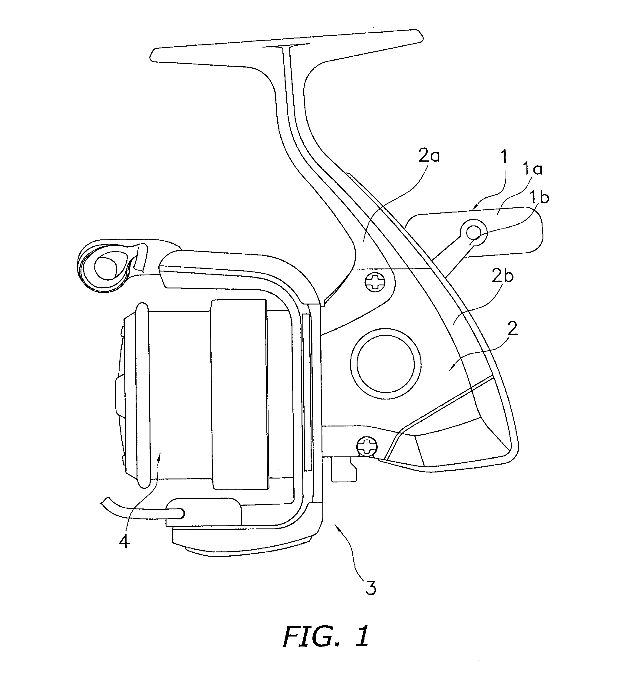
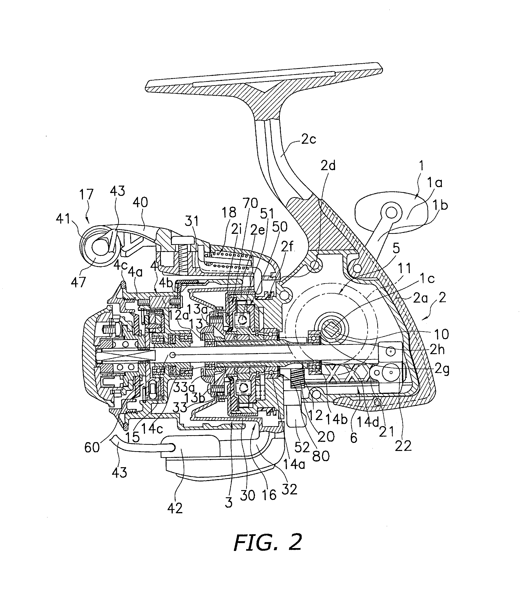
[0026]As shown in FIG. 1 and FIG. 2, a spinning reel of this embodiment of the present invention is equipped with a handle 1, a reel main body 2 that supports the handle 1 in such a way that the handle 1 can freely rotate, a rotor 3, and a spool 4. The rotor 3 is supported on the front portion of the reel main body 2 in such a way that the rotor 3 can freely rotate. The spool 4 retracts a fishing line onto its outer peripheral surface and is placed on the front portion of the rotor 3 in such a way that the spool 4 can freely move frontward and rearward. In FIG. 1 the handle 1 is attached to the left side of the reel main body 2, and in FIG. 2 the handle 1 is attached to the right side of the reel main body 2. In this way, the handle 1 can be attached to either the left side or the right side of the reel main body 2.

[0027]The handle 1 has a T-shaped handle knob 1a and a handle arm 1b. The handle knob 1a is attached to the distal end of the handle arm 1b in such a way that the handle ...

second embodiment

[0074]As shown in FIG. 8 and FIG. 9, a spinning reel of this embodiment of the present invention is equipped with a handle 101, a reel main body 102 that supports the handle 101 in such a way that the handle 101 can freely rotate, a rotor 103, and a spool 104. The rotor 103 is supported on the front portion of the reel main body 102 in such a way that the rotor 103 can freely rotate. The spool 104 retracts a fishing line onto its outer peripheral surface and is placed on the front portion of the rotor 103 in such a way that the spool 104 can freely move frontward and rearward. In FIG. 8 the handle 101 is attached to the left side of the reel main body 102, and in FIG. 9 the handle 101 is attached to the right side of the reel main body 102. In this way, the handle 101 can be attached to either the left side or the right side of the reel main body 102.

[0075]The handle 101 has a T-shaped handle knob 101a and a handle arm 101b. The handle knob 101a is attached to the distal end of the ...


PUM


Abstract

A spinning reel waterproofing member is provided for waterproofing a space between a tubular portion and a rotating member of a spinning reel. The tubular portion is disposed on a front end of a reel main body. The rotating member is disposed on an inner peripheral portion of the tubular portion and a front portion of the tubular portion. The spinning reel waterproofing member includes a main body portion being fixed to the inner peripheral portion of the tubular portion and including a distal end portion, a first lip portion extending in a radial direction so that the distal end portion of the main body portion is in contact with an outer peripheral portion of the rotating member, and a second lip portion extending in an axial direction from a front surface of the first lip portion toward a rear surface of the rotating member.

Description

CROSS-REFERENCE TO THE RELATED APPLICATIONS[0001]This application claims priority to Japanese Patent Application Nos. 2012-027430 and 2012-045630 filed on Feb. 10, 2012 and Mar. 1, 2012 respectively. The entire disclosure of Japanese Patent Application Nos. 2012-027430 and 2012-045630 is hereby incorporated herein by reference.BACKGROUND[0002]1. Technical Field[0003]The present invention relates to a spinning reel waterproofing member, particularly a spinning reel waterproofing member that waterproofs spaces between a tubular portion disposed on a front end of a reel main body of a spinning reel and a rotating member disposed on an inner peripheral portion of the tubular portion and a front portion of the tubular portion, and to a spinning reel using the waterproofing member.[0004]2. Related Art[0005]A spinning reel generally has a reel main body that is arranged to be attached to a fishing rod, a handle that is mounted on the reel main body in such a way that the handle can freely ...

Claims


Application Information

Patent Timeline
Patent Type & Authority Applications(United States)
IPC IPC(8): F16J15/32A01K89/00
CPCA01K89/00F16J15/3204A01K89/0117A01K89/01F16J15/324A01K89/011221
Inventor OCHIAI, KOJI
Owner SHIMANO INC
Why Eureka
Try Eureka