Medical imaging apparatus

a medical imaging and apparatus technology, applied in the field of medical imaging apparatus, can solve the problems of severely restricted patient vision field and/or angle of vision, and achieve the effect of shortening the visual range of an observer and not affecting the patient's vision

Inactive Publication Date: 2013-08-15
SIEMENS AG
View PDF16 Cites 13 Cited by
  • Summary
  • Abstract
  • Description
  • Claims
  • Application Information

AI Technical Summary

Benefits of technology

[0023]It is proposed that the image is projected on a face of the detector unit facing the observer and / or on a face of the housing unit enclosing the detector unit facing the observer. It is possible in this manner to extend the visual range of an observer, for example of a patient, to a region concealed by the detector unit. Also the medical imaging apparatus can thus have a virtual viewing window at least to some degree, the virtual viewing window being generated by projecting and / or displaying regions and / or objects, which are concealed in particular by the detector unit, on the projection surface unit. This can give the observer, for example the patient and / or a further person, the optical impression of being able to see through the medical imaging apparatus, at least to some degree.
[0024]It is also proposed that the image is displayed on the projection surface unit with little delay. This allows a live transmission of images on the projection surface unit to be achieved. It also allows visual contact and / or optical communication to be established between the patient and a person looking after said patient. As an alternative or in addition to the visual contact or optical communication, acoustic communication can also be established between the patient and the person looking after said patient. It also allows a patient not to feel enclosed within the receiving region, at least to some degree.
[0025]It is also proposed that a sequence of a number of images is displayed at a speed of at least 25 images per second on a projection surface unit. This allows the individual images to be displayed to the observer, in particular to the patient, in the form of a film, thereby suggesting transparency of the medical imaging apparatus to the observer.

Problems solved by technology

A further negative experience for the patient during the magnetic resonance examination is that the field of vision and / or angle of vision of the patient is severely restricted due to the positioning of the patient in the cylindrical receiving region.

Method used


Image

  • Medical imaging apparatus
  • Medical imaging apparatus
  • Medical imaging apparatus

Examples


Embodiment Construction

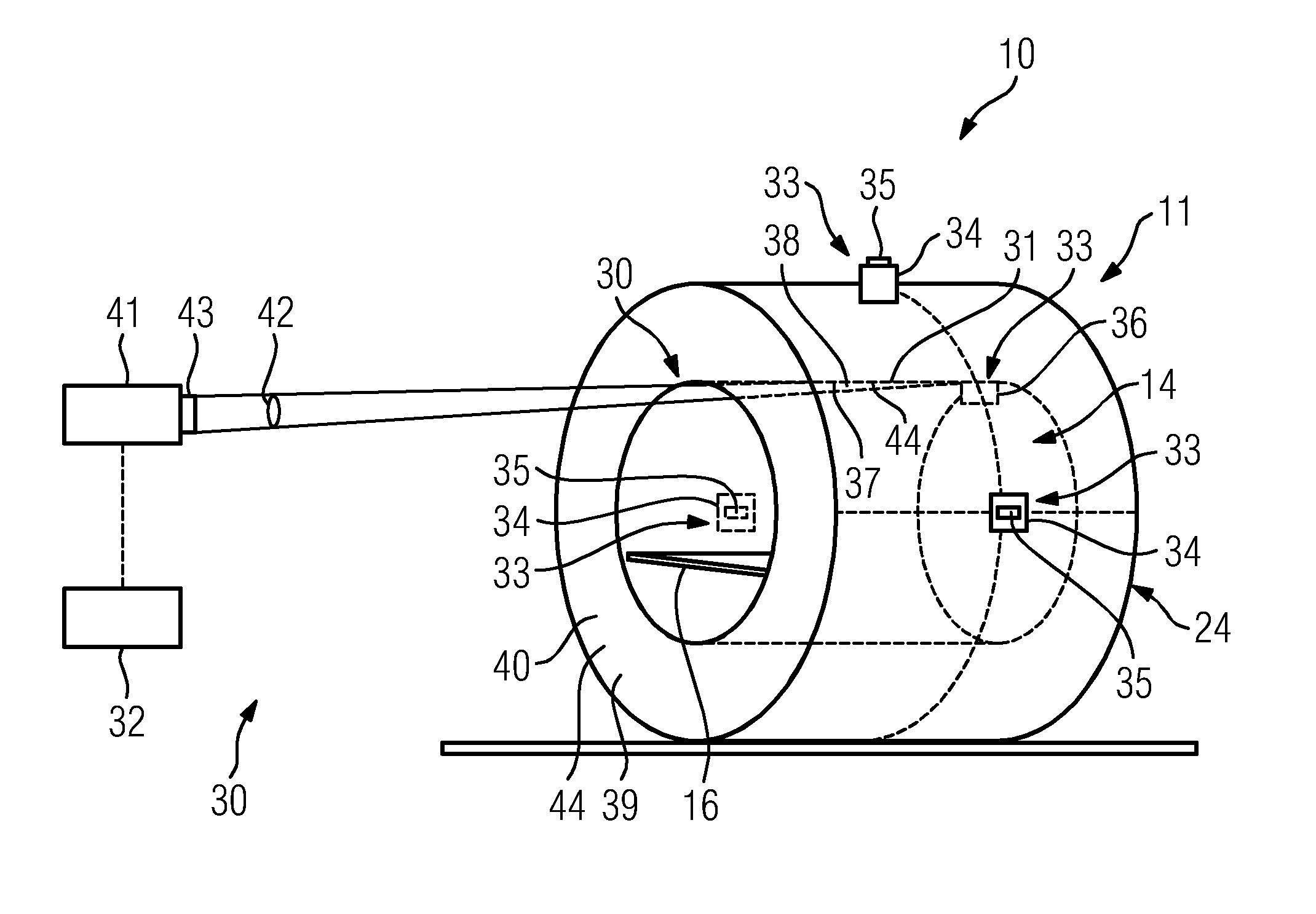
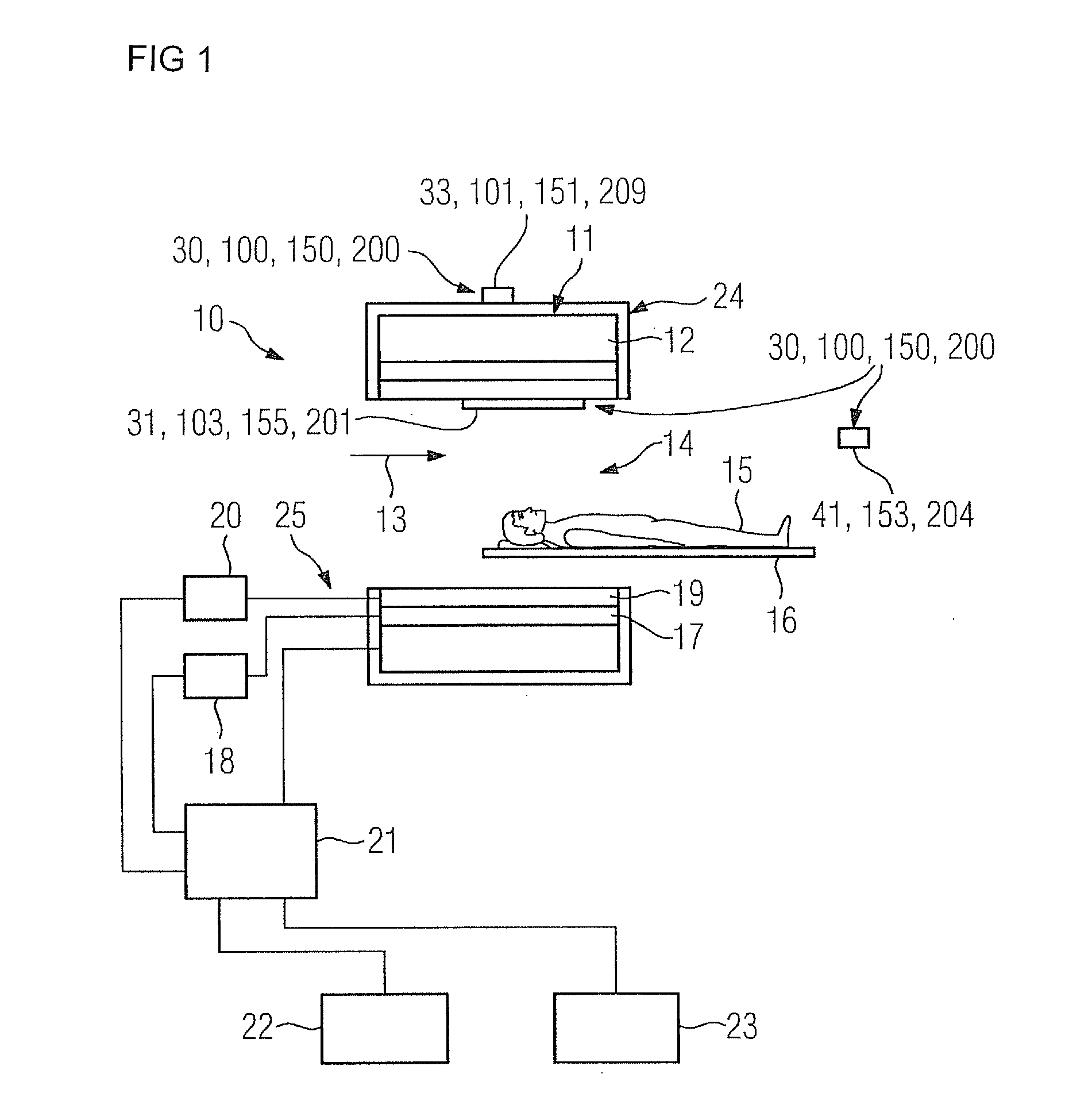
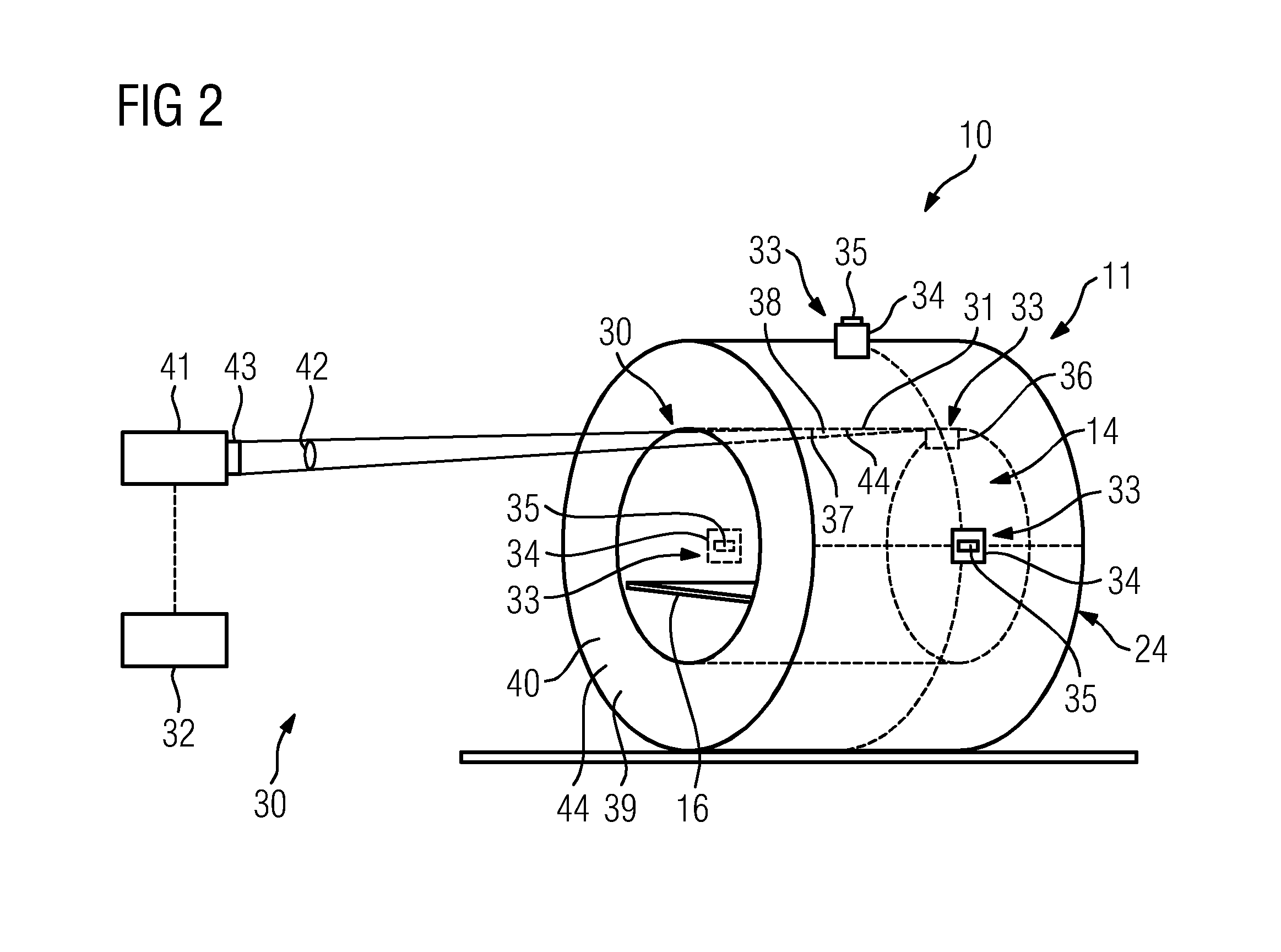
[0035]FIG. 1 shows a medical imaging apparatus 10, which is formed by way of example by a magnetic resonance apparatus. Alternatively the medical imaging apparatus 10 can also be formed by a computed tomography apparatus and / or a PET apparatus, etc.

[0036]The magnetic resonance apparatus comprises a detector unit formed by a magnet unit 11, having a main magnet 12 to generate a powerful and in particular constant main magnetic field 13. The magnetic resonance apparatus also has a cylindrical receiving region 14 to receive a patient 15, the receiving region 14 being enclosed in a cylindrical manner in a circumferential direction by a housing unit 24 of the magnetic resonance apparatus enclosing the magnet unit 11. The patient 15 can be conveyed into the receiving region 14 by means of a patient couch 16 of the magnetic resonance apparatus. The patient couch 16 is disposed in a movable manner within the magnetic resonance apparatus for this purpose.

[0037]The magnet unit 11 also has a g...


PUM


Abstract

A medical imaging apparatus includes a detector unit and a housing unit enclosing the detector unit. A cylindrical receiving region is provided for receiving a patient. The receiving region is enclosed in a cylindrical manner by the housing unit enclosing the detector unit. A projection unit is provided that has at least one projection surface unit, on which images of objects disposed outside the detector unit and the housing unit enclosing the detector unit are displayed to generate a virtual viewing window for an observer.

Description

CROSS REFERENCE TO RELATED APPLICATIONS[0001]This application claims priority of German Patent Office application No. 102011087265.5 DE filed Nov. 29, 2012. All of the applications are incorporated by reference herein in their entirety.FIELD OF INVENTION[0002]The illustrated embodiments relate to a medical imaging apparatus, in particular a magnetic resonance apparatus, having a detector unit, a housing unit enclosing the detector unit, a cylindrical receiving region to receive a patient, the receiving region being enclosed in a cylindrical manner by the housing unit enclosing the detector unit, and a projection unit.BACKGROUND OF INVENTION[0003]To examine a patient using medical imaging, in particular using magnetic resonance, it is necessary for the patient to be positioned within a cylindrical receiving region of the magnetic resonance apparatus for the duration of the magnetic resonance examination. This cylindrical receiving region typically has a diameter of 70 cm. The patient...

Claims


Application Information

Patent Timeline
Patent Type & Authority Applications(United States)
IPC IPC(8): G03B21/14
CPCG03B21/14G01R33/283A61B5/0555A61B5/055
Inventor KIMMLINGEN, RALPH
Owner SIEMENS AG
Why Eureka
Try Eureka